Up next in 10

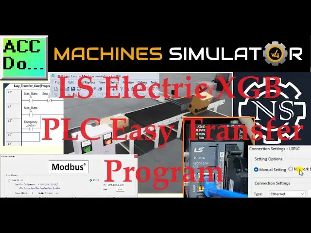
We will use Modbus TCP (Ethernet) to connect and program the XGB PLC to the Machine Simulator Easy Transfer Line. The Machine Simulator (EasyPLC) Software Suite is a comprehensive package with PLC, HMI, and Machine Simulator software. It features a Machine Simulator (MS) that allows virtual communication with many programmable logic controllers (PLCs) in a 3D world with real-time graphics and physical properties. Our PLC programming example will follow the five steps to PLC program development.
We will use the simulator's pre-built easy transfer line machine to learn PLC programming. We will develop ladder logic, connect via Modbus TCP, and test our program using the free XG5000 PLC programming software and XGB PLC. Let's begin!
Our website post provides effortless access to all the relevant links discussed in the video. We have gathered all the necessary information for your convenience, to all the resources mentioned.
https://accautomation.ca/ls-electric-xgb-plc-easy-transfer-program/
00:00 LS Electric XGB PLC Easy Transfer Program
01:16 Define the task: (Step 1 - XGB PLC Easy Transfer Line PLC Practice)
03:48 Define the Inputs and Outputs: (Step 2 - XGB PLC Easy Transfer Line PLC Practice)
05:53 Develop a sequence of operation: (Step 3 - XGB PLC Easy Transfer Line PLC Practice)
07:13 Develop the ladder logic PLC program (Step 4 - XGB PLC Easy Transfer Line PLC Practice)
13:15 Test the program: (Step 5 - XGB PLC Easy Transfer Line PLC Practice)
The Machine Simulator (EasyPLC) Software Suite Series can be found here...
https://accautomation.ca/series/easyplc-software-suite/
Some previous posts include the following:
EasyPLC Installing the Software
https://accautomation.ca/easyplc-installing-the-software/
https://youtu.be/EbWS_elbI2w
Show More Show Less View Video Transcript
0:00
We will use Modbus TCP Ethernet to connect and program the XGB PLC to the Machine Simulator
0:12
Easy Transfer line. The Machine Simulator Easy PLC software suite is a comprehensive package with HMI, PLC
0:21
and Machine Simulator software. It features a Machine Simulator, or MS, that allows virtual communication with many programmable
0:28
logic controllers, or PLCs, in a 3D world with real-time graphics and physical properties
0:34
Our PLC programming example will follow the five steps to PLC program development
0:40
We will use the Simulator's pre-built Easy Transfer line machine to learn PLC programming
0:46
We will develop ladder logic, connect via Modbus TCP, and test our program using the
0:51
free XG5000 PLC programming software and XGB PLC. Let's begin. Detailed information contained in this video can be found at accautomation.ca
1:04
A link has been put in the description below. If you have not watched the other videos yet, there will be links in the description below
1:09
that will start you with video 1. There will be links to the rest of the videos in this series as well
1:17
Step 1. Define the Task The first step of PLC programming development
1:23
is to define the task to determine what must be done. The Machine Simulator or Easy PLC software suite contains the Easy Transfer line example
1:32
in the Machine Simulator. This is just one of many machines with the software so you can learn and develop your
1:37
PLC programming skills. Launch Machine Simulator 4 and access the Machine's menu
1:45
The 01 Easy Transfer Line option will be seen on the pre-configured machines
1:50
We will program this machine. As you move your mouse around the machine picture, you can select the icon on the top
1:58
right side. This will show you the machine description. The photocell detects high boxes and sends them to the second conveyor, using the pneumatic pusher
2:11
Conveyors are activated with digital output 1. They will also include the panel control
2:16
The green start light will be on when the system is ready to run
2:20
When the start is pressed, the stop light will be on to indicate how the system is to
2:24
be stopped. Pressing the emergency stop button will turn off both lights and stop the sequence
2:31
The Machine Simulator has a demo mode for this built-in machine. Select Close from the machine description window
2:39
Select the demo mode for the Easy Transfer Line. This mode shows you the operation so you can better understand what needs to be accomplished
2:49
Press the control buttons in the simulator to operate the machine. Take some time to explore the 3D virtual environment using the navigation menu at the top of the window
2:57
The default selection allows you to move freely without colliding into any components, while
3:01
the first-person and third-person modes provide different perspectives. Exploring the demo mode will help you understand how the Easy Transfer Line operates
3:11
This will help you develop the PLC program to control the machine's actions effectively
3:17
Once we understand the task and have familiarized ourselves with the easy transfer operation
3:22
we can proceed to the next step in developing the XGB PLC program using the XG5000 programming software
3:30
By following these steps and gaining hands-on experience with the Machine Simulator Learning
3:34
Suite and the XGB, you'll be well on your way to mastering PLC programming and applying
3:39
your knowledge to real-world scenarios. So let's continue our journey and move on to the next step in the process
3:48
Step 2 – Define the Inputs and Outputs The written version specifies that we will require 4 digital outputs and 5 digital inputs
3:57
for our Easy Transfer Line. Inputs are signals or data received by the PLC, while outputs are signals or data sent
4:04
by the PLC to control external devices. By understanding the inputs and outputs, you can develop a program that reads the status
4:11
of the inputs and activates the appropriate outputs. While still in demo mode, select the UIO to display the inputs and outputs required for
4:19
this machine. These PLC IOs are for the machine's physical running and do not include the additional
4:25
bits or registers that may be required for programming. This will show you the digital outputs on the left side of the screen and the digital
4:35
inputs on the right side. If you are unsure what an output or input is doing, start the Easy Transfer Line machine
4:43
in Start Mode. Select View I.O. along the top of the Easy Transfer Line Machine Simulator window
4:57
You can manually run the Easy Transfer Line without any control or PLC connection
5:03
Select the outputs on the left to turn on and monitor the inputs on the right
5:09
Defining the inputs and output establishes the communication between the PLC and external devices
5:15
This allows the PLC program to monitor the inputs and continuously decide based on their status
5:21
The program can then activate the appropriate outputs to control the Easy Transfer Line operation
5:28
It is important to note that PLC programs operate cyclically, meaning they continuously
5:33
read the inputs and set the outputs. This ensures that the program is responsive to system changes and can adapt accordingly
5:41
By understanding the inputs and outputs and their relationship to the overall system
5:45
you can develop a logical sequence of operation for the Easy Transfer Line PLC program
5:49
This is our next step. Step 3. Develop the Logical Sequence of Operation
5:59
A flowchart or sequence table is used to understand the processes that need to be controlled thoroughly
6:04
It must also answer questions like the following. What happens when electrical power and or pneumatic air is lost
6:12
What happens when inputs and output devices fail? Do we need redundancy
6:18
Knowing all these answers up front is vital in developing the PLC program
6:22
This is the step where you can save a lot of work by understanding everything about the operation
6:27
It will help prevent you from continuously rewriting the PLC program logic
6:32
Here is a sequence table for the Easy Transfer Line. You read the input conditions and then look to the right hand side for the outputs that
6:40
will be set. The following line will then look for the input conditions again
6:48
As a programmer, it is vital to have a comprehensive understanding of the machine's sequence
6:52
and operation before starting the programming process. This can be achieved by asking questions or reviewing existing documentation to ensure
7:00
a clear understanding of the logical steps involved. This step sets the foundation for the subsequent development of the XGB PLC program which will
7:08
be covered in the next section. Step 4. Develop the PLC Program
7:20
Writing the ladder logic code for the PLC example will be the next step in our program development
7:25
Start the XG5000 programming software and start a new project. This can be done by selecting the new project under the Project tab on the main menu, using
7:35
the shortcut CTRL-N, or the New Project icon on the main ribbon
7:43
We will name the project and select XGB PLC for our program
8:01
Comments can be added for future reference
8:11
Select OK. Our scanned program will be displayed. Under the LS PLC that we selected the program, select Global, Direct Variables
8:22
We can now enter the variables for our machine simulator easy transfer line
8:51
To aid in setting the variables, you can see that once an address is entered, we can
8:56
highlight it, click and drag to populate the other variables below it
9:03
The Modbus addresses that we will use will match the settings for the communication to
9:07
the XGB PLC. Here is the map. These addresses will be written when we set up the communication and Modbus server
9:17
As we program, remember to save your work often. Select the Scan Program tab
9:25
We can now create our ladder logic program using the inputs and output icons on the menu bar
9:31
As we enter the instructions, we can select the variables. Starting and stopping the conveyor is done with the set and reset instruction
10:36
When the emergency stop is activated, both lights are turned off. This indicates to the operator that the emergency stop must be reset
10:54
When the photocell sees the high boxes, this activates the pneumatic pusher
10:58
When the pusher reaches the extended position, it will reset the pneumatic pusher
11:07
An end statement will indicate that this is where the program ends and to repeat the scan
11:12
Save your program. It is important to always save your program during programming
11:18
Double click on the internal FENet or Fast Ethernet network port. This will call up the standard settings for the port
11:28
Under the Basic tab, we can assign the IP address and settings to work with our network
11:40
Select the Smart Server for the server mode. This will include the Modbus server
11:46
Select the Modbus Settings button. Change the default Modbus address settings to those we have selected for our program
12:06
Select OK. We can now connect and transfer the program to our XGB PLC
12:15
If you are unsure of the connection to the XGB, we can use the network browsing to discover
12:19
the IP address. Once the PLC is discovered on our network, we can select OK
12:27
You can now select OK or connect from the Connection Settings window
12:34
You can also use the Connect from the main menu. The bottom bar of the XG5000 programming software will turn green indicating that the PLC is
12:42
connected and in Run mode. Select Write from the Online option in the main menu
12:51
You will then stop the PLC and transfer the program and settings like Modbus into the controller
13:08
We now have the PLC ready to test. Step 5. Test the program
13:20
To ensure the functionality and accuracy of the XG PLC practice program for an EZ-Transfer
13:25
line machine, it is essential to test the program thoroughly. Utilizing Machine Simulator or MS is an effective way
13:35
Using the MS you can simulate the operation of the EZ-Transfer line machine without needing
13:39
physical hardware, minimizing the risk of damage during the testing phase. You will use Modbus TCP on our LS XGB PLC to communicate with the EZ-PLC machine simulator
13:52
Call up the EZ-Transfer line machine simulator in Start mode. The status of the machine simulator will be at the bottom of the screen
14:01
Currently we have no PLC connected. Select I0 Drivers on the top middle of the screen
14:11
The Machine Simulator I0 number will be displayed. Here we select more I0 than is required for the EZ-Transfer line machine
14:18
The EZ-PLC driver is selected by default. Under the driver pulldown, select Modbus driver
14:26
This driver will communicate Modbus TCP or Ethernet in Modbus RTU serial
14:34
Select the configure button. We can now enter the information for our Modbus driver
14:41
Select TCP IP. This means that the Ethernet port on the computer will communicate with the XGB PLC
14:49
The digital inputs from MS to the XGB PLC will be MX3216 to MX3219
14:58
Digital outputs from the MS to the XGB PLC will be MX6416 to MX6420
15:06
Select the OK button. You will now see the inputs and outputs specified for the Modbus driver
15:14
You can now manually assign the driver outputs to the PLC inputs and then the driver inputs
15:19
to the PLC outputs. However, the automatic assignment works well and will save you time
15:25
Select automatic assignment from the driver option in the main menu. This will automatically assign the PLC simulator I0 to the machine simulator I0
15:36
Select Start Driver and exit from the main menu. On the bottom left side of the window, the driver communicates with the XGB PLC with
15:45
a green light. Select View I0 to see the machine simulator's input and output status
15:52
Ensure that the XGB PLC is in Run mode. We can now operate the Easy Transfer Line machine
15:59
The inputs and outputs of the MS will correspond to the PLC controller
16:05
Using Machine Simulator or MS to test the program will ensure that our program works
16:10
Troubleshooting is quickly done without any damage to physical hardware. This testing phase is critical in ensuring the safe and reliable operation of our Easy
16:19
Transfer Line machine. You can practice your modification and debug by modifying the Easy Transfer Line machine
16:27
operation in the following way. Add a counter for the large box conveyor to show the total
16:33
The control panel will need a reset button for this count. Calculate the rate of these boxes and boxes per hour
16:42
Let me know how you made out in the comments below. If you enjoyed this video, please hit the like button below
16:50
If you have any questions about the video, please leave a comment below and I'll do my best to answer it
16:55
If you want more information about us, or you want our free ebooks on numbering systems
16:59
or robust data logging, please click on the link in the description below to get it
17:03
A new video is uploaded every Monday, so make sure you hit the subscribe button to
17:07
get more videos like this in the future. Remember to click the bell beside your subscription to actually receive those notifications
17:14
Thanks so much for watching. I'll see you next time. Stay safe
#Manufacturing
#Networking
#Programming
#Education
#Factory Automation
#Other