Up next in 10

Wiring and Testing Our: P1-M622-16DR Practical Tutorial!
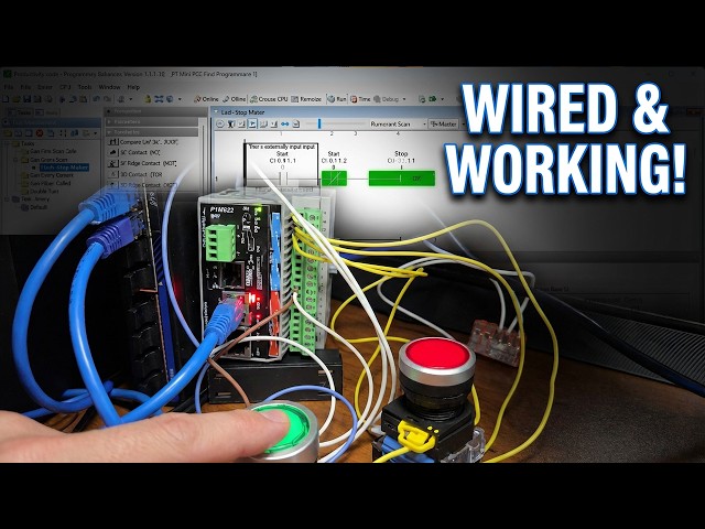
This video details wiring and testing a start-stop motor circuit on a P1M622-16DR mini PLC. Learn about the hands-on process of electrical wiring as we connect real-world devices, including start and stop push buttons, and an LED representing the motor output. We'll systematically test the program in stop mode, verifying our connections and understanding the core principles of programmable logic controller applications. This practical plc programming tutorial is a must-watch for anyone interested in industrial automation and ladder diagram implementation.
Master wiring and testing our on the P1-M622-16DR. Step-by-step tutorial with real-world examples.
📖 FULL WRITTEN TUTORIAL + DOWNLOADS
https://accautomation.ca/wiring-and-testing-our-p1-m622-16dr-practical-tutorial/
⏱️ TIMESTAMPS
0:00 - Wiring and Testing Our: P1-M622-16DR Practical Tutorial!
0:51 - Understanding Our Circuit Wiring
2:16 - P1-M622-16DR Terminal Block Layout
2:59 - Why Use Ferrules?
3:45 - Wiring the Start Pushbutton
4:15 - Wiring the Stop Pushbutton
4:57 - Wiring the LED Output (Motor Indicator)
5:44 - Testing in PLC Stop Mode
8:27 - Testing in PLC Run Mode
10:58 - Troubleshooting Common Issues
📚 WHAT YOU'LL LEARN
Show More Show Less View Video Transcript
0:03
We will now look at wiring and testing
0:05
our first ladder logic program with the
0:07
P1 M622 IO 16DR mini PLC. Having created
0:12
our start stop motor circuit and learned
0:14
about the monitoring tools in the
0:15
productivity suite software, it's time
0:17
to connect real world devices and see
0:19
our program in action. We will wire a
0:22
start push button, a stop push button,
0:24
and an LED to represent our motor
0:25
output. Then we'll systematically test
0:27
everything. First in stop mode to verify
0:29
our wiring, then in run mode to watch
0:31
the ladder logic execute. This is the
0:33
exciting part where the software meets
0:35
the hardware. Let's get started.
0:37
Detailed information contained in this
0:39
video can be found at acccca.ca.
0:42
A link has been put in the description
0:44
below. The website offers extensive
0:46
links, references, and coding samples,
0:48
making it a one-stop shop for all your
0:50
automation queries.
0:53
Understanding our circuit wiring.
0:56
Before we start wiring, let's understand
0:58
what we're connecting and why. Our start
1:00
stop motor circuit uses start push
1:03
button DI0.1.1
1:06
normally open. The start button is wired
1:07
as a normally open NO contact. When you
1:10
press it, it closes the circuit and
1:12
sends a signal to the PLC input. In our
1:14
latter logic, we use a normally open
1:16
contact instruction. When the physical
1:17
button is pressed, the contact closes,
1:19
allowing power to flow through the rung.
1:22
Stop. push button. DI0.1.1.2
1:25
normally open. Here's where beginners
1:27
often get confused. The physical stop
1:29
button is wired as normally open, but in
1:30
our latter logic, we use a normally
1:32
closed NC contact instruction. Why? We
1:36
want to demonstrate that we can change
1:37
the PLC's logic. The stop input in our
1:40
logic must remain active when no one
1:42
touches it. This is why we use the
1:44
normally closed contact in the program.
1:46
Note, wiring a normally open stop push
1:49
button to any PLC is not a failsafe
1:51
design. If the wire breaks or comes
1:53
loose, the circuit will not treat this
1:55
as a stop condition and will not shut
1:57
down the motor. We will change this in a
1:59
later post. LED light motor DO0.11.1.1.
2:03
The LED represents our motor contactor.
2:05
When the PLC output turns on, the LED
2:08
illuminates, simulating the motor
2:09
running. In a real application, this
2:11
output would control a motor starter or
2:13
contacttor coil.
2:15
The P1 M6226DR terminal block layout.
2:19
The P1M62216DR
2:21
uses an 18 position removable terminal
2:23
block for field wiring. The terminal
2:26
block accepts wire sizes from 30 to 16
2:28
gauge for solid conductors or 28 to 16
2:31
gauge for stranded wire. Strip length
2:34
should be approximately 6 to 7 mm. The
2:36
terminal layout is arranged as follows.
2:38
Inputs eight points. Terminals 1 to 8.
2:41
Input points 1 through 8. C1 common for
2:44
all eight inputs. Power terminal marked
2:46
plus 24 volts DC positive. Terminal
2:49
marked 24 volts DC negative. Outputs
2:52
eight points. Terminals for outputs 1
2:55
through 8. C2 common for all eight relay
2:57
outputs. Why use fererals? We are using
3:00
20 gauge stranded wire. The use of
3:02
fererals is vital in industrial
3:03
automation. Vibration resistance. In
3:06
industrial environments, machinery
3:08
vibration can cause bare stranded wire
3:10
to fatigue and loosen over time. A
3:12
crimped fereral provides superior strain
3:15
relief, optimal conductivity. The
3:17
crimping process deforms the wire and
3:19
fereral together, maximizing surface
3:21
contact area and minimizing electrical
3:23
resistance. Maintenance efficiency.
3:26
Fuels allow for repeated insertion and
3:28
removal without degrading the wire end,
3:30
making troubleshooting and field
3:31
upgrades significantly faster.
3:34
Professional standards using ferals
3:36
aligns with UL and IEC standards,
3:38
ensuring the control cabinet meets the
3:40
highquality benchmarks required for
3:42
modern automation systems.
3:45
Wiring the start push button. The start
3:48
push button is a momentary normally open
3:50
switch. Here's how to wire it. Connect
3:52
one side of the push button to the 24
3:54
volts DC positive supply. Connect the
3:57
other side of the push button to input
3:58
one on the terminal block DI0.11.1.
4:02
The input common C1 should be connected
4:05
to 24V DC negative ground. When you
4:08
press the button, 24 volts DC flows
4:10
through the closed contact to the input,
4:12
registering as on in the PLC.
4:16
Wiring the stop push button.
4:18
The stop push button is also wired as a
4:20
normally open momentary switch. Connect
4:22
one side of the push button to the 24V
4:25
DC positive supply. Connect the other
4:27
side of the push button to input two on
4:30
the terminal block DI0.1.1.2.
4:33
The input common C1 is already connected
4:35
to ground from the previous step.
4:37
Remember, even though the physical
4:39
button is normally open, the ladder
4:40
logic uses a normally closed contact.
4:43
When the button is not pressed, the
4:45
input is off, but the NC contact in the
4:47
ladder is true closed. When you press
4:50
the stop button, the input turns on,
4:52
making the NC contact false open, which
4:54
breaks the circuit and stops the motor.
4:58
Wiring the LED output motor indicator.
5:01
The LED represents our motor output.
5:03
Connect the LED's positive terminal to
5:05
output one on the terminal block DO01.1.
5:09
Connect the negative side of the LED to
5:11
ground through a current limiting
5:12
resistor, typically 470 ohms to 1
5:14
kiloohms for 24V DC. Since we are
5:17
connecting to an LED module with a
5:19
built-in resistor, we can connect
5:20
directly. The P1 M62216DR
5:23
has relay outputs rated for 6 to 30 volt
5:25
DC or 6 to 120 volts AC at 1 amp per
5:28
point. For our LED test, we're well
5:31
within the specified limits. Important,
5:33
the relay outputs are form a single pole
5:35
single throw contacts. You need to
5:38
provide your own external power source
5:40
for the output devices. The relay simply
5:42
switches this power on and off.
5:45
Testing in PLC stop mode. Before we run
5:48
our program, we need to verify that all
5:50
wiring is correct. This is a critical
5:52
step that many beginners skip. Don't
5:54
make that mistake. Testing in stop mode
5:56
lets us check our IO without the program
5:58
running. Step one, put the PLC in stop
6:01
mode. Turn the CPU selector switch to
6:03
the stop position. The run LED on the
6:05
CPU should turn off. Step two, open data
6:08
view. In Productivity Suite, open the
6:10
data view panel. Tools, jot, data view,
6:14
or control plus shift + F3. You can also
6:17
use the IO view for a graphical
6:19
representation of all inputs and
6:21
outputs. Step three, test input one,
6:24
start push button. Press and hold the
6:27
start push button. Watch the data view.
6:29
DI0.11.1
6:31
should change from off, unchecked, to
6:33
on, checked. The input LED on the PLC
6:36
front panel should also illuminate.
6:38
Release the button and verify it returns
6:40
to off.
6:41
This confirms your start button wiring
6:43
is correct. Step four, test input two,
6:46
stop push button. Press and hold the
6:49
stop push button. Watch DI0.1.1.2
6:53
in data view. It should change from off
6:55
to on. Release and verify it returns to
6:57
off. In the latter logic, the stop will
7:00
change from on to off when the normally
7:02
closed contact is pressed. When we
7:04
release the stop button, the ladder
7:05
logic contact returns to on. This
7:07
confirms your stop button wiring is
7:09
correct. Step five, force the output to
7:12
test LED wiring. Now, we need to test
7:14
the wiring for our output. Since we're
7:16
in stop mode, the program isn't running.
7:18
So, we'll manually force the output on.
7:21
In data view, find DO0.1.1.
7:24
Check the edit checkbox. Check the force
7:26
checkbox. Check the value check box to
7:28
set it on. Click the send edits button.
7:31
The LED will not illuminate. However,
7:33
the ladder logic will show that the
7:35
output will be on. So we can only check
7:38
the outputs when running our program.
7:39
When a productivity PLC is in stop mode,
7:42
the CPU stops scanning the application
7:44
logic. Consequently, output modules are
7:46
typically set to a safe state, usually
7:48
off, to prevent unintended machine
7:50
operation. If we need to check each
7:53
output separately, we can use the end
7:55
statement after each one. The program
7:56
will only scan until the end statement
7:58
before returning to the start of the
8:00
latter logic. As each output is
8:02
confirmed, we can remove the end
8:04
statements. Step six, remove the force.
8:06
Uncheck the force check box for DO0.1.1
8:09
and click send edits to remove the
8:11
force. The LED should turn off. If you
8:14
are enjoying this video, please hit the
8:16
like button below. Keeping up with all
8:18
the latest automation innovations can be
8:20
difficult, so hit the subscribe button.
8:22
Remember to hit the bell beside your
8:23
subscription to receive the
8:24
notifications.
8:26
Testing in PLC run mode. Now that we've
8:30
verified all our input wiring is
8:31
correct, let's run the program and watch
8:33
the ladder logic execute. Step one, put
8:36
the PLC in run mode. Turn the CPU
8:38
selector switch to the run position. The
8:40
run LED on the CPU should illuminate
8:42
green. Step two, enable monitoring in
8:45
the ladder editor. Ensure you click the
8:47
monitor icon in the task window toolbar.
8:50
Your ladder logic will now show
8:51
real-time states with green on and red
8:54
off indicators. Step three, open data
8:57
view IO. Keep the data view panel open
8:59
so you can see the tag values change in
9:01
real time alongside the ladder logic.
9:03
Step four, test the start stop sequence.
9:06
Test the start function. Press the start
9:07
push button. Watch DI01.1.1
9:11
turn on green in the ladder and data
9:13
view. The output DO0.1.1
9:17
should turn on. The LED should
9:18
illuminate. Release the start button.
9:20
The output should stay on because of the
9:21
ceiling contact. Test the seal circuit
9:24
with the motor running. LED on. Observe
9:26
the ladder logic. You'll see DI0 pair
9:28
1.1.1 start is off. Red because you
9:31
released the button. DO01.1.1
9:35
seal contact is on green. This is
9:37
keeping the circuit energized. DI0.1.1.2
9:41
stop NC contact is true. Green because
9:44
the stop button is not pressed. DO01.1
9:49
motor output is on. Green. Test the stop
9:52
function. Press the stop push button.
9:53
Watch DI01.1.2
9:56
turn on in data view. The NC contact in
9:59
the ladder opens. Turns red. The output
10:01
DO0.11.1.1
10:03
turns off. The LED turns off. Release
10:05
the stop button. The motor stays off
10:07
until start is pressed again.
10:09
Understanding what you're seeing. As you
10:11
test, pay attention to these key
10:12
observations. The seal contact in
10:15
action. When you press start
10:16
momentarily, the motor turns on and
10:18
stays on. This is because the output
10:20
DO0.1.1
10:22
feeds back as a parallel contact with
10:24
the start button. Once the output is on,
10:26
it holds itself on. This is called a
10:29
seal or latch circuit. The NC stop
10:31
contact. The stop button uses a normally
10:32
closed contact in the ladder even though
10:34
the physical button is normally open.
10:37
Watch what happens. Stop not pressed
10:39
input is off but NC contact is true
10:42
closed allows current flow. Stop pressed
10:46
input is on. NC contact is false open
10:48
breaks the circuit. The priority of stop
10:50
over. Start. Try this. Hold both buttons
10:52
at the same time. The motor will not
10:55
run. Stop always wins because the NC
10:57
contact is in series with the circuit.
10:59
This is intentional safety design.
11:03
Troubleshooting common issues. LED
11:06
doesn't light when forced. Check the
11:07
polarity of your wiring. LEDs are
11:09
polarized. Verify the current limiting
11:11
resistor value. Confirm that the output
11:14
common has a return path to ground.
11:16
Input doesn't register when the button
11:18
is pressed. Verify 24 volts DC is
11:21
present at the button. Check the common
11:22
C1 connection to ground. Inspect wire
11:25
connections at the terminal block. Motor
11:27
starts but won't seal. Verify the seal
11:29
contact address matches the output
11:30
address. Check that the output is
11:32
actually turning on. Watch the LED.
11:34
Motor won't stop. Verify the stop button
11:36
is wired to the correct input. Confirm
11:39
the ladder uses an NC contact for stop.
11:41
Check for a stuck start button. Next
11:43
time we will look at using online
11:45
editing programming to modify our
11:47
program with or without the PLC scanning
11:49
the logic. The Productivity Mini PLC
11:53
series from Automation Direct and
11:54
specifically the P1 M62216DR
11:58
is a compact powerhouse that packs
12:00
serious capability into a surprisingly
12:02
small footprint. To see our first ladder
12:05
logic, click here. Click here to build
12:06
digital twins of 3D virtual machinery,
12:08
test control logic, and learn automation
12:10
without expensive hardware using machine
12:13
simulator.
#Industrial Materials & Equipment
#Industrial Materials & Equipment
#Factory Automation
#Electromechanical Devices