0:04
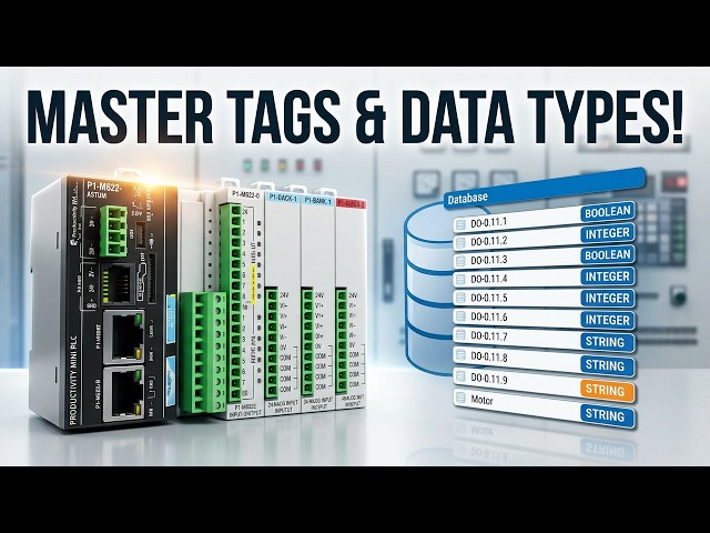
We will now look at the tag numbering
0:05
systems used with the Productivity Mini
0:07
PLC P1 M622 16DR. The Productivity Suite
0:12
software allows us to use tags in the
0:14
PLC. Tags are a method for assigning and
0:17
referencing memory locations numbering
0:19
systems within the programmable logic
0:21
controller. They allow a more structured
0:23
programming approach and are stored
0:24
within a tag database. The tag database
0:26
is stored in the memory of the
0:28
Automation Direct productivity series
0:30
PLC's. Do not overthink tags. Tags are
0:33
just names that we assign to variables,
0:35
numbering systems of any data type
0:37
stored in the PLC memory. Throughout
0:40
this series, we've been using tags like
0:42
start, stop, and motor for our start
0:44
stop circuit. These meaningful names
0:46
make our program much easier to read and
0:48
understand than cryptic memory
0:50
addresses. In this video, we'll explore
0:52
the tag database in depth. How to create
0:54
tags, understand data types, and
0:56
efficiently organize our programs
0:58
memory. Let's get started. Detailed
1:00
information contained in this video can
1:02
be found at accautomation.ca.
1:05
A link has been put in the description
1:07
below. The website offers extensive
1:09
links, references, and coding samples,
1:11
making it a one-stop shop for all your
1:12
automation queries. accutomation.ca.
1:17
Data types. Productivity numbering
1:20
There are multiple data types available
1:22
for configuring parameters and tags
1:24
within your automation project.
1:26
Understanding these data types is
1:28
crucial for efficient memory usage and
1:30
accurate data handling. Here is a list
1:31
of the available types. Boolean, true or
1:34
false, one or zero, on or off. These are
1:37
used for discrete IO point tag names as
1:40
well as internal tag names used for
1:42
logic control. Every switch, push
1:44
button, relay output, and internal flag
1:46
in your program is a boolean, integer, 8
1:48
bit unsigned. These whole or natural
1:50
numbers range from 0 to 255, 0 to FF
1:52
hexadimal. They are used for numerical
1:55
tags when only positive variables will
1:57
be used within a bite boundary. Examples
2:00
include small counters or status codes.
2:04
Integer 16 bit signed. The range is
2:10
These are used for numerical tags where
2:12
variables have the potential for
2:13
negative or positive values. Useful for
2:16
temperature readings that might go below
2:18
zero or position offsets. Integer 16 bit
2:21
unsigned. The range is 0 to 65,535.
2:25
These are used for tags that will only
2:27
have a positive value. Common for timer
2:29
preset values or production counters.
2:32
Integer 16 bit. The unsigned binary
2:35
coded decimal will have the range of 0
2:37
to 9,9.99. These will be used for tags
2:40
that can only be represented by the
2:41
decimal numbering system. 09 for each
2:44
digit. often used when interfacing with
2:46
older equipment or displays that expect
2:51
Integer 32-bit signed. The range is
2:54
negative 2 bill147,483,648
2:58
to 2 bill147,483,647.
3:03
This is used as the default for most
3:05
numeric tags that have the potential for
3:07
both negative and positive values. The
3:09
larger range makes this suitable for
3:11
production counters that might
3:12
accumulate large numbers over time. In
3:15
TEDR 32bit BCD, unsigned binary coded
3:18
decimal will have the range of 0 to
3:23
These will be used for tags that can
3:24
only be represented by the decimal
3:26
numbering system. 09 for each digit.
3:30
Float 32-bit. This uses the IE format
3:33
floating point number ranging from 3.39
3:35
* 10 to the exponent 38 to 3.39 * 10 to
3:38
the exponent 38. This data type is for
3:41
tags that need decimal precision such as
3:44
analog sensor readings, flow rates,
3:46
pressure measurements, or mathematical
3:47
calculations requiring fractional
3:51
String asy or text representation, which
3:54
allocates one bite, 8 bits per
3:56
character. These are used for tags that
3:58
are words when using instructions like
4:00
asy, email, and LCD displays. Strings
4:03
are essential for operator messages,
4:05
part numbers or data logging constant.
4:07
This is a fixed value for a numeric or
4:12
Constants can be integers, floatingoint
4:14
or strings. When you enter the constant,
4:16
the field defined by the data entered
4:17
assumes the range. Examples
4:21
1 equals 32-bit signed integer. 1.0
4:25
equals floating point. The letter A
4:28
equals a string. For a deeper
4:30
understanding of number systems, check
4:32
out this post which explains the meaning
4:34
behind the types of numbers listed
4:38
Tag database productivity numbering
4:40
systems. Open the tag database by
4:42
clicking on the tag database under the
4:44
right program heading in the application
4:46
tools. You can also use the main menu
4:49
edit tag database to access the tag
4:52
The tag database is the centralized
4:54
location where all your program
4:56
variables are defined and documented.
4:59
for the P1 M622 16DR. This includes the
5:02
eight integrated discrete inputs, eight
5:04
relay outputs, and any internal memory
5:06
locations you create.
5:09
Tags to show productivity numbering
5:11
systems. This upper part of the tag
5:14
database window will help you to find
5:16
the tags and information that you
5:20
Show all. This will show all of the tags
5:22
in your entire project. Every input,
5:24
output, internal bit, timer, counter,
5:29
Invert. This will invert all of the
5:31
selected tag types. If the input type,
5:33
like discrete inputs, is checked and you
5:35
hit the invert button, the tag will be
5:37
unchecked. If the input type is
5:39
unchecked and you invert, then it will
5:41
be checked. This is useful for quickly
5:43
switching between viewing different
5:46
Search field. The tags field will allow
5:48
you to search the database for a
5:50
particular name or phrase. For example,
5:52
typing motor would filter to show only
5:54
tags containing that word. Tag type
5:56
filters. You can select specific
5:58
categories to view. Discrete inputs,
6:00
your eight built-in DC inputs, discrete
6:03
outputs, your eight relay outputs,
6:05
integers, all numeric variables, floats,
6:09
decimal numbers, strings, text,
6:12
constants, and many more.
6:19
mini PLC, the most commonly used filters
6:22
are discrete inputs and discrete outputs
6:24
since these correspond to the physical
6:26
IO built into the CPU. Note the P1 M622
6:31
16DR uses the addressing format
6:35
for inputs and DO0000.1x
6:38
for outputs where X ranges from 1 to 8.
6:42
Editor productivity numbering systems.
6:45
The editor has the following columns of
6:47
information. Not all columns may be
6:49
visible by default. You can customize
6:51
which ones you see. Name. Name was given
6:54
to the applicable tag. This is what you
6:56
see in your ladder logic. Examples
6:58
start, stop, motor, running. Type data
7:01
type used by the tag, boolean, integer,
7:03
float, etc. Str indicates the type of
7:06
structure used single, array, etc.
7:09
System ID, internal ID assigned to
7:11
userdefined tags. This is managed
7:13
automatically by the software. IO
7:15
address the respective assigned IO
7:17
address for the P1 M6226DR.
7:24
Outputs D1 1.1 through D01.1.8.
7:29
Rows the number of rows applicable to a
7:31
2D array data type. Calls the number of
7:34
columns applicable to a 1D or 2D array
7:37
data type. Numchars, the number of
7:39
characters applicable to a string data
7:41
type. Retentive checkbox indicating if
7:44
the tag is retentive. If power is lost
7:46
or removed from the PLC, this determines
7:48
if the information in the tag is
7:49
retained or not. Critical for production
7:52
counters and system state variables that
7:54
must survive power cycles. In it value
7:56
entered in this field will be used for
7:58
the initial value upon a cold start or
8:00
power up. Wire label. Use this field to
8:04
indicate the wire label information for
8:06
the IO point. This is invaluable for
8:08
maintenance. You can document which
8:09
physical wire or terminal connects to
8:11
each point. Mod start, optional Modbus
8:14
starting address. We specify what
8:16
information can be shared on the network
8:18
through Modbus communication protocols.
8:20
Mod end optional Modbus ending address.
8:23
Forceable allows the tag to be forced
8:25
using data view. A maximum of 64 tags
8:29
may be selected as forcable at any given
8:31
time. We used this feature when testing
8:33
our wiring in stop mode. In it forced
8:36
allows the tag to be forced upon startup
8:38
from a power cycle or stop run
8:39
transition. In it forced value entered
8:42
in this field will be used for the tags
8:44
value upon an initial force. Comment use
8:47
this field to add comments associated
8:48
with the tag. Detailed comments make
8:50
troubleshooting much easier months or
8:52
years after the program was written.
8:54
Remote access checkbox that indicates
8:56
the tag can be monitored remotely via
8:58
the CPU data remote monitor app. Default
9:01
format used with integers allows data to
9:03
be viewed in various formats. For
9:04
example, decimal, hex, etc. In use,
9:08
checkbox indicates the tag is used in
9:09
the latter diagram. This helps identify
9:11
unused tags that can be cleaned up.
9:15
Customizing the tag database view. Right
9:18
clicking on the column name will bring
9:20
up a menu with several options. Auto
9:22
resize columns automatically adjust
9:24
column widths to fit the content. Select
9:26
columns. Choose which columns are
9:27
visible or hidden. Sort. Sort the tags
9:30
alphabetically or by other criteria.
9:32
Hide show columns. Quickly toggle column
9:35
visibility. You can also manually resize
9:38
columns by clicking between column
9:39
headers and dragging. Want to see tags
9:41
organized your way? Simply click and
9:43
drag column headers to rearrange them in
9:45
any order that makes sense for your
9:49
Adding and managing tags. At the bottom
9:52
of the tag database window, you'll find
9:54
several important buttons. Add tags. We
9:57
can add tags of any data type. Tags can
9:59
be made individually or grouped together
10:01
in arrays. We'll be discussing arrays
10:03
and functions later in this series. When
10:05
you create a new tag, you'll be prompted
10:07
to define its name, type, and initial
10:09
properties. Delete tags remove a tag
10:12
from the tag database. Be careful.
10:13
Deleting a tag that's in use will create
10:15
errors in your program until you replace
10:17
it. Reset table. Restore the table to
10:20
original default settings. This is
10:22
useful if you've rearranged columns and
10:24
want to start fresh. Help. Explore the
10:26
help menu for tag database. The built-in
10:28
documentation is comprehensive and
10:32
If you are enjoying this video, please
10:34
hit the like button below. Keeping up
10:36
with all the latest automation
10:37
innovations can be difficult, so hit the
10:39
subscribe button. Remember to hit the
10:40
bell beside your subscription to receive
10:45
Practical example. Understanding P1 M622
10:48
and 16DR addressing. Let's look at how
10:51
our start stop motor circuit uses the
10:53
tag database. When we configured the
10:56
hardware, the productivity suite
10:57
automatically created tags for our
10:59
integrated IO. DI0.1.1
11:03
was automatically assigned. DI0.1.1.2
11:07
was automatically assigned. DO0.11
11:10
was automatically assigned. We then
11:12
renamed these to meaningful names.
11:15
became start. DI0.1.12
11:20
became motor. The addressing format for
11:27
where X is 18 for the eight inputs.
11:31
where X is 18 for the eight outputs. The
11:34
format breaks down as follows. The first
11:36
number 0 equals the system number.
11:38
Second number 1 equals the rack number.
11:40
The third number 1 equals the slot
11:42
number. The fourth number X equals the
11:44
point number 1 to 8. If you expand with
11:47
additional IO modules, the P1M62216DR
11:51
supports up to four expansion modules.
11:53
Those will have different slot numbers
11:55
reflecting their position in the system.
11:58
Memory available in the P1M62216DR.
12:05
provides generous memory resources, user
12:07
memory, 50 megbytes, includes program
12:09
data and documentation. Memory type,
12:12
flash, and batterybacked RAM. Retentive
12:15
memory 512 kilobytes. This is far more
12:18
than enough for most small to medium
12:19
automation applications. You could
12:22
create thousands of tags and still have
12:23
plenty of memory remaining. The
12:25
batterybacked RAM ensures that retentive
12:27
tags maintain their values even during
12:32
Best practices for tag names. From my
12:34
experience programming hundreds of
12:36
PLC's, here are some recommendations.
12:39
Use descriptive names. Conveyor one
12:41
motor is better than M1. Follow a naming
12:43
convention. Be consistent across your
12:45
entire project. Avoid special
12:48
characters. Stick to letters, numbers,
12:50
and underscores. Document everything.
12:52
Use the comment field extensively. Group
12:55
related tags. Consider prefixes like
12:59
related tags. The tag database allows
13:01
you to manipulate and view all of the
13:03
system and personal tags that you have
13:05
developed. Mastering the tag database is
13:08
essential for creating organized,
13:09
maintainable programs. Next time we will
13:11
look at contact and coil instructions in
13:13
the Productivity Mini PLC P1N M6226DR.
13:17
The Productivity Mini PLC series from
13:19
Automation Direct and specifically the
13:23
is a compact powerhouse that packs
13:25
serious capability into a surprisingly
13:27
small footprint. To see our first ladder
13:30
logic, click here. Click here to build
13:32
digital twins of 3D virtual machinery.
13:34
Test control logic and learn automation
13:36
without expensive hardware using machine