0:02
In this tutorial, I am going to walk you
0:04
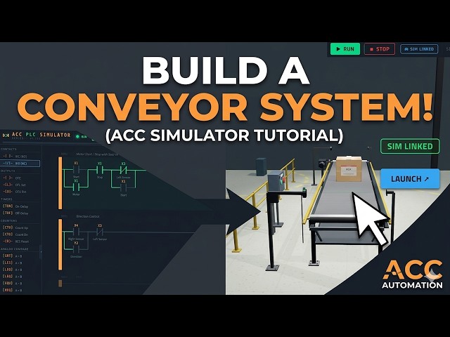
through the conveyor scene in the ACC
0:06
PLC simulator using the five-step PLC
0:08
program development framework.
0:12
This is a single-axis belt conveyor with
0:14
proximity sensors at each end and a box
0:16
that travels back and forth along the
0:18
By the end, you will have a complete
0:20
working program built step by step the
0:22
same way I approach every PLC project.
0:26
Detailed information contained in this
0:27
video can be found at accautomation.ca.
0:30
A link has been put in the description
0:33
The website offers extensive links,
0:35
references, and coding samples, making
0:37
it a one-stop shop for all your
0:40
Once again, that is accautomation.ca.
0:43
Input and output IO overview.
0:47
The conveyor scene has six IO points,
0:49
four inputs and two outputs.
0:52
X1 is your start push button wired
0:54
normally open. X2 is your stop push
0:56
button wired normally closed. X3 is a
0:58
proximity sensor at the left end of the
1:00
belt. X4 is a proximity sensor at the
1:03
right end. On the output side, Y1
1:05
controls the motor. When Y1 is on, the
1:08
>> Y2 controls direction. When Y2 is off,
1:11
the box travels forward from left to
1:12
right. When Y2 is on, the box travels in
1:15
reverse from right to left.
1:18
Step one, define the task.
1:21
Write down in plain English what the
1:23
system must do before you touch any
1:26
The conveyor must start when the
1:27
operator presses start and stop when the
1:29
operator presses stop. When running, the
1:31
box travels forward from left to right.
1:34
When the box reaches the right sensor,
1:36
the conveyor automatically reverses
1:37
direction. The box then travels in
1:39
reverse from right to left. When the box
1:42
reaches the left sensor, the conveyor
1:43
stops automatically. The operator can
1:45
press start again to repeat the cycle.
1:48
The stop button must stop the conveyor
1:50
at any time regardless of where the box
1:53
Step two, define the IO.
1:56
List every input and with its address
1:59
and description. X1 is start, X2 is stop
2:02
normally closed, X3 is the left sensor,
2:04
X4 is the right sensor, Y1 is motor run,
2:08
Four inputs and two outputs. No analog
2:11
IO is needed for this application. The
2:13
IO map is already defined by the scene,
2:15
so this step is done.
2:18
Step three, develop a flowchart or
2:20
sequence of operations.
2:22
Map out the sequence of operations.
2:24
First, the operator presses start.
2:26
The motor starts with the direction set
2:27
to forward. The box travels left to
2:29
right. The box arrives at the right
2:32
The direction reverses. The box travels
2:34
right to left. The box arrives at the
2:36
left sensor. The motor stops.
2:38
The system is ready for the next cycle.
2:40
The stop button can interrupt the motor
2:42
at any point and immediately stop it.
2:45
Step four, develop the PLC program.
2:48
Translate the flowchart into ladder
2:50
logic. Wrong zero is your motor start
2:53
X1, the start button, is a normally open
2:56
contact in parallel with Y1 for the seal
2:58
in. X2, the stop button, is a normally
3:00
open contact in series with the normally
3:03
Then we add X3, the left sensor, as a
3:06
normally closed contact in series. And
3:08
here's the important part.
3:10
We add X1 in parallel with that normally
3:12
closed X3 contact. The output is Y1,
3:14
motor run. The normally closed X3
3:16
contact is your automatic stop.
3:18
>> When the box arrives at the left sensor,
3:20
X3 goes true. The normally closed
3:21
contact opens and Y1 drops out. But
3:24
after the cycle completes, the box is
3:26
sitting at the left sensor. X3 stays
3:28
true. Without X1 in parallel, the motor
3:31
would never start again.
3:33
With X1 in parallel, pressing start
3:35
bypasses the left sensor and the motor
3:37
>> Wrong one is your direction control.
3:40
X4, the right sensor, is a normally open
3:42
contact. Y2, the direction output, is in
3:44
parallel as a seal in, so the direction
3:47
stays reversed after the box moves away
3:49
from the right sensor.
3:51
Add Y1, motor run, as a normally closed
3:53
contact in series with the seal in
3:55
branch. This [music] resets the
3:56
direction when the motor stops, so the
3:58
next cycle starts in the forward
4:00
The output is Y2, direction.
4:03
If you are enjoying this video, please
4:04
hit the like button below. Keeping up
4:06
with all the latest automation
4:07
innovations can be difficult, [music] so
4:09
hit the subscribe button.
4:11
Remember to hit the bell next to your
4:12
subscription to receive notifications.
4:18
Step five, test the program.
4:20
Connect the conveyor scene and run the
4:22
full test sequence. Put the simulator in
4:24
run mode. Press start.
4:27
The belt starts moving forward. Watch
4:29
the box travel to the right.
4:32
The box hits the right sensor and the
4:33
direction reverses automatically. The
4:36
box travels back to the left. The box
4:38
hits the left sensor and the motor stops
4:42
Press start again and the cycle repeats.
4:48
Now, press stop during travel.
4:50
The motor stops immediately. Test the
4:52
stop button at every stage, forward
4:53
travel, reverse travel, and at each
4:55
sensor position. If any step does not
4:57
work, use step mode in the simulator.
4:59
Toggle the inputs manually and press
5:01
step to see exactly which contacts are
5:07
The conveyor scene introduces IO
5:09
patterns you will see in every material
5:12
Motors, sensors, direction control, and
5:15
automatic sequencing. The five-step
5:17
framework kept our development organized
5:18
from task definition through testing.
5:21
Try modifying the program.
5:23
Add a counter to track how many complete
5:25
cycles the box has made.
5:27
Add a timer to pause for 2 seconds at
5:29
each end before reversing.
5:32
These are fundamental building blocks
5:33
for more complex machines.
5:36
Head over to accautomation.ca/simulator
5:39
to try the conveyor scene yourself.
5:41
The link is in the description.
5:44
If you found this helpful, subscribe to
5:45
ACC Automation for more PLC tutorials.
5:49
And leave a comment telling me what
5:51
program you would like to build next.
5:54
Many PLC manufacturers offer a range of
5:56
hardware and software.
5:58
All programmable logic controllers share
6:00
similar basic features. To see how I
6:02
would approach learning about basic
6:06
Click here to see how you can continue
6:08
programming for free with the ACC PLC
6:10
simulator featuring 3D scenes you can