Up next in 10

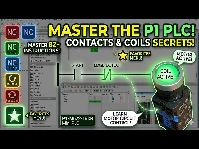
Master contact and coil instructions on the P1-M622-16DR. Step-by-step tutorial with real-world examples. Contact and coil instructions are in every PLC program. The Productivity Suite Software comprises more than 82 instructions, organized into 13 categories for the PLC. Contacts and Coils are two of those categories. Contact instructions include NO, NC, NO Edge, NC Edge, and Compare. Coil instructions include Out, Set, Reset, OR Out, Flasher, Debounce, Timed, Toggle, Program End, and No Operation.
We will be looking at these instructions in the Productivity Mini PLC P1-M622-16DR. We will also look at how to organize your frequently used instructions using the Favorites feature. Throughout this post, we will tie each instruction back to our start-stop motor circuit so you can see exactly how they apply to real programs. Let's get started.
📖 FULL WRITTEN TUTORIAL + DOWNLOADS
https://accautomation.ca/p1-m622-16dr-mini-plc-contact-and-coil-instructions/
⏱️ TIMESTAMPS
0:00 P1-M622-16DR Mini PLC – Contact and Coil Instructions!
1:07 Favorites – Contact and Coil Instructions
2:04 Contacts – Contact and Coil Instructions
5:36 Coils – Contact and Coil Instructions
10:34 Applying What We've Learned to Our Start-Stop Circuit
📚 WHAT YOU'LL LEARN
✅ P1-M622-16DR Mini PLC – Contact and Coil Instructions! on the Productivity PLC
✅ Practical, hands-on approach
✅ Real-world tips from manufacturing experience
🔗 MORE RESOURCES
▶ Series: https://accautomation.ca/series/productivity-plc/
Show More Show Less View Video Transcript
0:03
Contact and coil instructions are in
0:05
every PLC program. The Productivity
0:08
Suite software comprises more than 82
0:10
instructions organized into 13
0:12
categories for the PLC.
0:14
Contacts and coils are two of those
0:15
categories. Contact instructions include
0:17
NO, NC, NO edge, NC edge, and compare.
0:21
Coil instructions include out, set,
0:23
reset, or out flasher, debounce, timed,
0:26
toggle, program end, and no operation.
0:29
We will be looking at these instructions
0:31
in the Productivity mini PLC P1M6-22
0:34
or 16DR. We will also look at how to
0:37
organize your frequently used
0:38
instructions using the favorites
0:40
feature.
0:41
Throughout this post, we will tie each
0:43
instruction back to our start-stop motor
0:45
circuit so you can see exactly how they
0:47
apply to real programs.
0:49
Let's get started. Detailed information
0:51
contained in this video can be found at
0:52
accautomation.ca.
0:55
A link has been put in the description
0:57
below. The website offers extensive
0:58
links, references, and coding samples,
1:00
making it a one-stop shop for all your
1:02
automation queries.
1:03
Once again, that is accautomation.ca.
1:09
Favorites, contact, and coil
1:11
instructions.
1:12
The favorites section is a heading found
1:14
under the instructions window of the
1:16
Productivity Suite software.
1:18
You can open the instructions window by
1:20
clicking on it in the application tools
1:21
panel or use the main menu, tools,
1:24
instructions list.
1:30
Right clicking any instruction in the
1:32
list opens a menu that lets you add to
1:34
favorites. Click that option and the
1:36
instruction will now appear under your
1:38
favorites heading at the top of the
1:40
list.
1:41
To remove an instruction from your
1:42
favorites, right click on it under the
1:44
favorites heading and select remove from
1:45
favorites.
1:47
Favorites are a great way to separate
1:48
the instructions you use most often from
1:50
the full list. As you work through this
1:52
series and build more complex programs,
1:54
you will find yourself reaching for the
1:55
same handful of instructions repeatedly.
1:58
Adding them to favorites saves time and
2:00
keeps your workflow organized.
2:05
Contacts, contact and coil instructions.
2:09
Contacts are the input conditions of a
2:11
rung. They represent the state of
2:12
boolean tags, physical inputs, outputs,
2:15
or internal bits, [music] and control
2:17
whether power flows through the rung to
2:18
the output coil.
2:20
The PLC evaluates logic from left to
2:22
right, top to bottom on each scan. For a
2:24
deeper understanding of how the PLC scan
2:26
works, see this post, understanding the
2:28
PLC program scan.
2:31
NO contact, NO, the normally open
2:33
contact enables power flow in a rung
2:35
when the contact is energized.
2:37
It disables power flow when the contact
2:39
is de-energized. This is the most common
2:41
contact in PLC programming. In our
2:43
start-stop motor circuit, the start
2:45
input DI0.1.1.1
2:48
uses an NO contact. When the physical
2:50
start push button is pressed, the
2:51
contact energizes and power flows
2:53
through the rung.
2:55
When the button is released, the contact
2:56
opens, but the sealing contact DO0.1.1.1
3:00
in the parallel branch keeps the rung
3:02
energized.
3:05
NC contact, NC, [music] the normally
3:07
closed contact enables power flow in a
3:09
rung when the contact is de-energized.
3:12
It disables power flow when the contact
3:14
is energized. This is where most people
3:16
get confused. Just think of a normally
3:17
closed contact as the opposite logic.
3:20
In our start-stop motor circuit, the
3:21
stop input DI0.1.1.2
3:24
uses an NO contact in the ladder. As we
3:27
covered in the online editing and
3:28
fail-safe wiring post, the physical stop
3:30
button is wired normally closed to the
3:32
input, meaning the input is energized on
3:35
or one in its normal state. An NO
3:37
contact in the ladder therefore passes
3:39
power continuously as long as the stop
3:42
button is not pressed.
3:44
When the stop button is pressed, the
3:46
physical NC contact opens, the input
3:48
drops to off, and the NO ladder contact
3:51
opens, breaking the rung.
3:54
This is the correct fail-safe approach.
3:56
A broken wire or failed button
3:57
de-energizes the input and stops the
3:59
motor automatically.
4:02
NO edge contact, NOE. The normally open
4:06
edge contact acts as a one-shot input on
4:08
either the rising edge or falling edge
4:10
of a signal.
4:11
It allows power flow for exactly one
4:13
scan when the contact transitions from
4:15
de-energized to energized, rising edge,
4:17
or energized to de-energized, falling
4:19
edge.
4:20
This is sometimes referred to as a
4:22
one-shot in PLC programming. It is
4:24
extremely useful when you need an action
4:26
to happen only once per button press.
4:28
For example, incrementing a counter each
4:30
time a button is pressed rather than
4:32
once per scan while it is held.
4:34
See this post for more details on
4:36
one-shot logic, how to make a one-shot
4:38
in the PLC.
4:40
NC edge contact, NCE. The normally
4:43
closed edge contact also acts as a
4:45
one-shot, but triggers on the transition
4:47
of a normally closed contact.
4:49
It allows power flow for one scan when
4:51
the contact transitions from energized
4:53
to de-energized, rising edge, or
4:56
de-energized to energized, falling edge.
4:59
Compare contact, CMP. This input contact
5:03
compares two numerical values. Based on
5:05
the selected operand, equal to, not
5:07
equal to, greater than, less than,
5:09
greater than or equal to, or less than
5:11
or equal to, it either enables or
5:13
disables power flow in the rung.
5:16
A practical example, if you have an
5:17
analog temperature sensor reading into
5:19
the P1M622
5:21
16DR via an expansion module, you could
5:24
use a compare contact to turn on a
5:26
cooling fan output when the temperature
5:27
tag exceeds a set point. The compare
5:30
contact makes numeric decisions directly
5:32
in your ladder logic without requiring a
5:34
separate math instruction.
5:37
Coils, contact and coil instructions.
5:40
Coils are the output elements of a rung.
5:42
When the rung conditions, contacts,
5:44
evaluate to true, the coil executes its
5:46
function.
5:47
The type of coil determines exactly what
5:48
that function is.
5:51
Out coil out provides an output that
5:53
directly responds to the current state
5:55
of the rung. When the rung is true, the
5:57
output is on. When the rung is false,
6:00
the output is off. This is the coil we
6:02
have been using throughout this series
6:04
for the motor output DO0.1.1.1
6:08
in our start-stop circuit.
6:10
The out coil also has a one-shot option,
6:12
which turns the output on for just one
6:14
scan during the transition from off to
6:16
on.
6:18
Set coil, set, sets the output into a
6:20
latched on condition when the rung is
6:22
enabled. Once set, the output remains on
6:24
even if the rung condition goes false.
6:27
Reset coil, RST, resets, unlatches, the
6:31
output of a corresponding set coil. The
6:33
output turns off when the reset rung is
6:35
enabled.
6:37
The set and reset instructions work
6:39
together and are an alternative way to
6:40
build a start-stop circuit. Rather than
6:43
using a ceiling contact with an out coil
6:45
as we did in our first program, you can
6:47
use a set coil on the start rung and a
6:49
reset coil on the stop rung.
6:51
Both approaches produce the same result.
6:53
The set-reset method can sometimes make
6:55
the logic easier to read in programs
6:57
with many interlocks.
6:59
See our first program post for the
7:00
ceiling contact approach, P1M622 16DR
7:04
mini PLC first program start-stop motor
7:06
circuit.
7:08
Or out, OR, allows an out coil with the
7:11
same tag to be used in multiple rungs.
7:13
When any rung with that tag is true, the
7:14
output turns on.
7:16
Note, while the OR out instruction is
7:18
available, [music] having the same
7:19
output tag controlled from multiple
7:21
rungs can make troubleshooting
7:22
difficult.
7:24
From my experience in the field, this
7:25
should be avoided in most cases. Keep
7:27
your outputs in a single rung where
7:29
possible. It makes maintenance and
7:30
troubleshooting much faster.
7:33
Flasher, FLS, cycles an output bit on
7:36
and off at a programmed rate. You set
7:38
the cycle time in milliseconds.
7:40
When the rung condition is true, the
7:41
output will be on for half the cycle
7:43
time and off for the other half.
7:46
For example, setting the cycle time to
7:48
1,000 milliseconds results in an output
7:50
that flashes 0.5 seconds on and 0.5
7:53
seconds off.
7:56
A practical use of the P1M622-16DR would
7:57
be to flash an indicator light wired to
7:59
one of the eight relay outputs to signal
8:01
an alarm or a mode change
8:05
without needing a timer instruction to
8:07
manage timing manually.
8:10
Debounce coil, DBN, eliminates output
8:12
coil chatter caused by rapid on-off
8:14
transitions at the rung condition.
8:17
The rung condition must remain
8:18
continuously on or off for the program
8:21
debounce time before the output
8:22
activates or deactivates.
8:24
Chatter occurs when logic allows a rapid
8:27
oscillation. For example, if a compare
8:29
contact is evaluating a value that is
8:31
bouncing just above and below the
8:33
comparison threshold.
8:36
In our example, the rung condition must
8:37
remain stable for 1,000 milliseconds, 1
8:40
second, before the output changes state.
8:43
This adds a deliberate delay that
8:45
filters out noise without needing a
8:47
separate timer.
8:49
Timed coil, TMC, holds the state of the
8:51
output on for a predetermined time after
8:53
the rung becomes true.
8:55
Even if the rung condition goes false
8:57
before the time expires, the output will
8:59
remain on until the time duration
9:01
completes.
9:02
An output maintained option is also
9:04
available, which keeps the output on
9:06
after the time period as long as the
9:07
rung condition remains true.
9:10
A practical example, pressing a
9:11
momentary push button could trigger the
9:13
time coil to hold a solenoid valve open
9:15
for exactly 5 seconds, regardless of how
9:17
briefly the button was pressed.
9:20
Toggle coil, TGC, changes the state of
9:23
the output each time the rung is
9:24
enabled. If the output is currently on,
9:26
it turns off.
9:28
If it is currently off, it turns on.
9:30
This is sometimes called a flip-flop
9:31
circuit. In our example, when the input
9:33
transitions from off to on, the output
9:35
toggles.
9:36
This is useful for applications where a
9:38
single push button needs to act as both
9:40
an on and off control, common in simple
9:42
lighting or fan controls. See this post
9:45
for the logic behind the flip-flop
9:47
circuit, creating a flip-flop circuit in
9:48
the PLC.
9:51
No operation coil, NOP, indicates that
9:54
the rung will have no operation. It is
9:56
used as a placeholder in ladder logic,
9:59
for example, when you are reserving a
10:01
rung for future expansion or temporarily
10:03
disabling a rung during development
10:05
without deleting it.
10:08
Program end coil, END, marks the end of
10:11
a task. The Productivity Suite software
10:13
automatically places an end coil at the
10:15
end of your program.
10:16
The PLC will execute all rungs up to the
10:18
end coil on each scan, then restart the
10:20
scan from the top.
10:22
If you are enjoying this video, please
10:24
hit the like button below.
10:26
Keeping up with all the latest
10:27
automation innovations can be difficult,
10:28
[music] so hit the subscribe button.
10:31
Remember to hit the bell beside your
10:32
subscription to receive the
10:33
notifications.
10:35
Applying [snorts] what we've learned to
10:36
our start-stop circuit.
10:39
Looking back at the start-stop motor
10:41
circuit we have built throughout this
10:42
series, you can now identify every
10:44
instruction by name. DI0.1.1.1,
10:48
start, NO contact, passes power when the
10:51
start button is pressed.
10:54
DI0.1.1.2,
10:55
stop, NC contact, passes power at all
10:58
times, opens when the stop button signal
11:01
is energized.
11:02
DO0.1.1.1,
11:04
motor sealing branch, NO contact,
11:07
holds the rung energized after the start
11:08
button is released.
11:10
DO0.1.1.1,
11:12
motor out coil, turns the relay output
11:15
on when the rung is true.
11:17
That single rung uses three of the
11:19
contact and coil instructions covered in
11:21
this post. As we build more complex
11:23
programs in the coming post, adding
11:25
timers, counters, and math, you will see
11:27
all of these instructions combined in
11:29
increasingly practical ways.
11:32
Next time, we will look at timer
11:34
instructions in the Productivity Mini
11:35
PLC P1 M622-16DR.
11:39
Many PLC manufacturers offer a range of
11:41
hardware and software.
11:43
All programmable logic controllers share
11:44
similar basic features.
11:47
To see how I would approach learning
11:48
about basic PLCs, click here.
11:51
Click here to see how you can program
11:53
for free with the ACC PLC simulator with
11:55
3D scenes you can program.
#Jobs & Education
#Factory Automation