0:03
What if you could practice real PLC
0:05
ladder logic right in your browser for
0:07
free with no hardware and no downloads?
0:10
The ACC PLC simulator lets you do
0:12
exactly that. And today I'm going to
0:14
walk you through the control panel scene
0:16
step by step so you can build and test a
0:18
real start, stop, jog circuit in
0:20
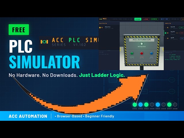
minutes. The ACC PLC simulator is a free
0:23
browserbased tool that runs entirely in
0:25
Chrome, Edge, or Firefox. It uses
0:27
standard PLC register conventions. X
0:30
registers for digital inputs, Y
0:32
registers for digital outputs, C
0:34
registers for internal relays, and it
0:37
even supports analog with AX and AY
0:39
registers. There's nothing to install
0:41
and nothing to license. You just open
0:43
the page and start programming. Here is
0:45
what makes it interesting. The simulator
0:47
comes with a 3D control panel scene.
0:49
It's a floor- mounted Nema 4 enclosure
0:51
with three push buttons and a motor run
0:53
pilot light. The green button is your
0:55
start push button wired to X1 as a
0:57
normally open momentary contact switch.
1:00
The red button is your stop push button
1:02
wired to X2 as a normally closed
1:04
momentary contact switch. And the blue
1:06
button is your jog push button wired to
1:08
X3, also normally open. On the output
1:11
side, Y1 drives the Motor Run pilot
1:13
light on the panel. When you open the
1:15
simulator, this scene connects
1:16
automatically through the browser. No
1:19
wiring and no configuration.
1:25
Detailed information contained in this
1:27
video can be found at
1:28
accccclautomation.ca.
1:30
A link has been put in the description
1:32
below. The website offers extensive
1:34
links, references, and coding samples,
1:36
making it a one-stop shop for all your
1:38
automation queries. accautomation.ca.
1:46
When you load the simulator, it comes
1:47
preloaded with a two-run start, stop,
1:49
jog program. This is classic PLC ladder
1:52
logic that every beginner needs to
1:58
Rung zero is your main control rung. It
2:00
has three parallel input branches. The
2:02
first branch is a normally open contact
2:04
on X1, your start button. The second
2:07
branch is a sealin path.
2:10
It uses a normally open contact on Y1 in
2:12
series with a normally closed contact on
2:17
And the third branch is a normally open
2:19
contact on X3. your jog button.
2:22
All three branches feed into a normally
2:24
closed contact on X2, your stop button.
2:27
And the output is an OTE instruction on
2:30
Y1, your motor run. Rung one is the jog
2:33
intermediate rung. It has a normally
2:34
open contact on X3 that drives an OTE
2:43
Let's walk through how the start and
2:47
When you press the green start button,
2:52
Power flows through the first branch
2:53
past the X2 stop contact and energizes
2:56
Y1. The motor run light turns on. Now,
2:58
here's the key part. When you release
3:00
the start button, X1 goes false. But Y1
3:03
is already true. So, the second branch,
3:05
the sealin path, keeps power flowing. Y1
3:09
stays on. That's your sealin latch. To
3:12
stop the motor, you press the red stop
3:14
button. X2 is normally closed, so it's
3:16
passing power in its normal state.
3:19
When you press stop, X2 goes false, the
3:22
normally closed contact opens, power is
3:24
interrupted, and Y1 drops out.
3:27
The motor stops, and the sealin is
3:35
Now, let's look at how the jog works.
3:37
This is the clever part of this circuit.
3:39
When you press the blue jog button, X3
3:41
goes true. That does two things at once.
3:44
In rung zero, the third branch
3:46
energizes, sending power to Y1. The
3:50
But in rung one, X3 also energizes C1.
3:53
And here's why that matters. Back in
3:56
rung zero, the sealin branch has a
3:58
normally closed contact on C1.
4:01
When C1 is true, that contact opens. The
4:03
sealin path is blocked. So, as long as
4:05
you hold the jog button, the motor runs.
4:07
But the moment you release it, X3 goes
4:10
false, C1 drops out, and Y1 turns off.
4:12
No latch. That's exactly how a real jog
4:15
function works on a factory floor. The
4:17
motor only runs while you hold the
4:19
button. It's a safety feature.
4:27
To connect the control panel scene to
4:29
the simulator, click the connect button
4:31
in the simulator toolbar. You'll see a
4:33
card for the control panel showing all
4:39
Click launch and the scene opens in a
4:43
The connection happens automatically
4:45
through the broadcast channel API.
4:46
You'll see the link badge turn blue and
4:51
Now every X input from the scene feeds
4:53
directly into the simulator and every Y
4:55
output from the simulator drives the 3D
5:05
Once connected, put the simulator in run
5:07
mode by pressing F5 or clicking the run
5:23
Now go to the scene window and press the
5:29
Watch the pilot light turn on.
5:32
Release it. The motor stays running
5:33
because of the seal in. Press the red
5:41
Now try the jog button. Hold it and the
5:44
motor runs. Release it and the motor
5:50
No latch. That's the entire circuit
5:53
working exactly the way it would on a
5:54
real PLC connected to a real control
5:59
If you're enjoying this video, please
6:00
hit the like button below. Keeping up
6:02
with all the latest automation
6:04
innovations can be difficult, so hit the
6:05
subscribe button. Remember to hit the
6:08
bell beside your subscription to receive
6:15
Let's recap what you just learned.
6:18
You built and tested a real start stop
6:20
jog circuit with a sealin latch. You
6:22
understand how normally open and
6:24
normally closed contacts work.
6:27
You know how internal relay C1 blocks
6:29
the seal in during jog to prevent
6:32
And you did it all in a browser for free
6:34
with a 3D control panel providing visual
6:38
This is exactly how PLC programs work in
6:41
the real world. Head over to
6:43
acccautomation.ca/simulator
6:46
to try the ACC PLC simulator yourself.
6:49
The link is in the description. If you
6:51
found this helpful, subscribe to ACC
6:53
Automation for more PLC tutorials and
6:56
leave a comment telling me what scene or
6:58
circuit you'd like to see next.