Up next in 10

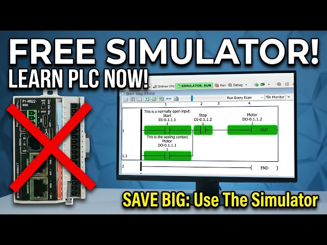
P1-M622-16DR Mini PLC: Your Simulator Adventure Starts Now!
Mar 23, 2026
Discover the power of the built-in PLC simulator and take your programming skills to the next level. The PLC simulator is a game-changer for professionals and students alike, allowing you to test and debug your programs in a virtual environment. Learn how to harness its capabilities and unlock new possibilities for automation and control. Get ready to explore the features and benefits of the built-in PLC simulator and find out how it can revolutionize your work. Whether you're a seasoned engineer or just starting out, this video will show you the incredible potential of the PLC simulator and how to use it to achieve your goals. Watch now and discover the power of the built-in PLC simulator for yourself.
Master your simulator adventure starts on the P1-M622-16DR. Step-by-step tutorial with real-world examples.
📖 FULL WRITTEN TUTORIAL + DOWNLOADS
https://accautomation.ca/p1-m622-16dr-mini-plc-using-the-productivity-suite-simulator/
⏱️ TIMESTAMPS
0:00 - P1-M622-16DR Mini PLC: Your Simulator Adventure Starts Now!
0:51 - What is the Productivity Suite Simulator?
2:26 - Opening Our Existing Project
3:00 - Starting the Simulator
4:03 - Transferring the Program to the Simulator
4:37 - Putting the Simulator in Run Mode
5:26 - Controlling Inputs Through the IO View
7:24 - Using Data View to Monitor and Modify
7:59 - Making Program Changes While Using the Simulator
11:13 - Stopping the Simulator and Returning to Hardware
12:11 - Why Use the Simulator?
Show More Show Less View Video Transcript
0:01
One of the most powerful features of the
0:03
Productivity Suite software is the
0:05
built-in PLC simulator. If you don't
0:07
have the physical P1 M622 16DR hardware
0:11
yet, or you're developing logic at your
0:13
desk before heading to the plant floor,
0:14
the simulator lets you program, modify,
0:17
and test your ladder logic without a
0:19
single piece of hardware connected. This
0:21
is a gamecher for learning, development,
0:23
and troubleshooting. We will now use the
0:25
start stop motor circuit we have already
0:27
built in this series to walk through the
0:28
simulator step by step. You'll see how
0:31
easy it is to run your program
0:32
virtually, toggle inputs in real time,
0:34
and verify your logic is working
0:36
correctly before you ever touch the
0:37
physical hardware. Let's get started.
0:40
Detailed information contained in this
0:41
video can be found at acccca.ca.
0:45
A link has been put in the description
0:46
below. The website offers extensive
0:48
links, references, and coding samples,
0:50
making it a one-stop shop for all your
0:52
automation queries. Remember, this all
0:55
can be found at acccca.ca.
0:58
What is the productivity suite
1:00
simulator?
1:01
The productivity suite simulator is a
1:03
built-in software feature that emulates
1:05
the behavior of a real productivity
1:07
series CPU directly on your computer.
1:10
Think of it as invisible hardware
1:12
sitting on your desk. The simulator
1:13
accepts your ladder logic program the
1:15
same way a physical PLC does. You
1:17
transfer the project to it, put it in
1:19
run mode, and your program starts
1:20
executing. The simulator supports the
1:23
full P1000, 2000, and 3000 CPU families,
1:26
including 1,000 CPUs and local IO stack.
1:30
All basic analog and discrete IO
1:32
modules, Modbus TCP server, or client
1:35
connections on your computer's Ethernet
1:37
port. You will need Productivity Suite
1:39
version 3.8 or higher. If you followed
1:41
along with our software installation
1:43
post in this series, you are already
1:45
set. The software is a free download
1:47
from Automation Direct. No license or
1:49
additional purchase required.
1:52
Simulator capabilities. Analog and
1:54
discrete IO simulation. Full data view
1:57
monitoring. Modbus TCP IP client or
1:59
server connections. Great for testing
2:01
HMI communication. Ladder logic
2:04
monitoring in real time. Current
2:06
simulator limitations to be aware of. No
2:08
intelligent modules. RS232485
2:12
ports are not simulated. PID
2:14
instructions are not supported. Motion
2:16
instructions are not supported. The
2:18
simulator will time out after 2 hours.
2:20
Plan your sessions accordingly.
2:23
For our start stop motor circuit, none
2:25
of these limitations applies. All we
2:28
need is discrete IO and the simulator
2:30
handles that perfectly.
2:33
Opening our existing project. We will
2:35
use the start stop motor circuit that we
2:38
created earlier in this series. If you
2:40
saved your project file, open it now in
2:42
the productivity suite software. You
2:43
should see our familiar ladder logic
2:45
with DI0.1.1
2:49
start normally open contact in ladder.
2:51
DI01.1.2
2:53
stop normally open contact in ladder.
2:56
DO0.11.1
2:58
motor output coil with ceiling contact.
3:01
If you don't have the save project, you
3:03
can quickly rebuild it. The first
3:04
program post in this series walks
3:06
through every step. Before starting the
3:08
simulator, let's set up our data view so
3:10
we have a good monitoring panel ready to
3:12
go. Right click on the rung in the
3:14
ladder editor and select monitor in data
3:16
view. Leave the selection set to create
3:18
a new tab. Then click okay. This will
3:21
automatically populate the data view tab
3:23
with all the tags from our rung start,
3:25
stop, and motor. Having this ready
3:27
before launching the simulator will save
3:29
time once the program is running.
3:31
Starting the simulator.
3:34
With the project open and data view set
3:36
up, we are ready to launch the
3:38
simulator. There are two ways to do
3:39
this. Select the simulator icon on the
3:42
main toolbar. Use the main menu. CPU
3:44
simulator.
3:46
A warning message will appear. This
3:49
simply means the program needs to be
3:50
transferred to the simulator before it
3:52
can run. Exactly the same process as
3:54
connecting to physical hardware. Select
3:56
okay. You will notice the status bar at
3:58
the bottom of the screen now shows that
4:00
you are online with the PLC simulator
4:02
sim. The toolbar icons will reflect an
4:05
online connection.
4:07
Transferring the program to the
4:08
simulator.
4:10
Just like a real PLC, the simulator
4:12
needs the program transferred to it
4:13
before it can run. Select the transfer
4:16
project to CPU icon on the toolbar or
4:18
use the main menu, file, transfer
4:20
project to CPU. The transfer dialogue
4:23
will appear and the program will
4:24
download to the simulator. This is the
4:26
same process you would follow with the
4:28
physical P1 M62216DR
4:31
connected over USBC or Ethernet. A great
4:33
habit to build. Once the transfer is
4:35
complete, click on the ladder logic
4:37
window and select monitor to enable live
4:39
ladder monitoring.
4:43
Putting the simulator in run mode. Now
4:46
select the run icon on the toolbar or go
4:48
to CPU run. A confirmation window will
4:51
appear asking if you want to place the
4:52
PLC simulator into run mode. Click yes.
4:55
Your ladder logic is now executing in
4:57
the simulator. Watch the ladder editor.
5:00
You will see the contacts and coils
5:01
display their current states just as
5:03
they would with real hardware connected
5:06
with the default display mode showing
5:08
green on and red off. Everything is
5:11
reading correctly. Start contact DI011.1
5:14
off red. Stop contact DI01.1.2
5:19
off red because it is a normally open
5:21
contact in our ladder. Motor output coil
5:24
DO01.1
5:26
off red. This is exactly what we would
5:29
expect. No inputs are active, so the
5:31
motor is off. Controlling inputs through
5:34
the IO view.
5:36
This is where the simulator really
5:37
shines. We can toggle inputs on and off
5:39
directly in the software to simulate
5:41
pressing physical buttons. Open the data
5:44
view panel if it isn't already visible.
5:45
Tools, data view, or the shortcut
5:47
control + shift + F3. In the data view
5:50
window, click the toggle IO view icon.
5:52
Then click the plus symbol to expand the
5:54
IO view panel. You will now see a
5:57
graphical representation of the P1
5:59
M62216DR's
6:00
IO in the simulator. Eight discrete
6:02
inputs and eight relay outputs laid out
6:05
just like the real module. Simulating
6:07
the stop button. Click on input 2DI0.1.2
6:11
in the IO view. This simulates not
6:14
pressing the stop button. Wired normally
6:16
closed.
6:18
Simulating the start button. Click on
6:20
input one DI01 1.1.1 in the IO view.
6:23
This simulates pressing the start
6:25
button. Watch the ladder logic window.
6:27
The start contact turns green. On the
6:29
motor output coil energizes turns green.
6:31
The ceiling contact DO0.1.1
6:35
in the second branch also turns green.
6:37
Latching the circuit. Now click input
6:38
one again to release it. Simulating
6:40
letting go of the start button. The
6:42
motor output remains on. The ceiling
6:45
contact is doing its job holding the
6:47
circuit energized exactly as it would in
6:49
the real wiring scenario. This is the
6:51
core behavior of a start stop motor
6:53
circuit and we have just verified it
6:55
without a single wire connected.
6:57
Simulating the stop button. Click on
6:59
input 2dis01 1.2 in the IO view. This
7:02
simulates pressing the stop button
7:04
because the stop contact on our ladder
7:06
is normally open. N O deenergizing input
7:09
2 opens the contact and breaks the rung.
7:11
Watch the ladder logic. The stop N O
7:14
contact opens, turns red. The motor
7:16
output coil deenergizes, turns red. The
7:18
ceiling contact drops out. Click input
7:21
two again to release the stop button.
7:23
The circuit is now back in its normal
7:25
state, ready to start again. The motor
7:27
remains off until start is pressed
7:30
using data view to monitor and modify.
7:34
The data view tab we created earlier
7:36
gives us an organized view of all three
7:37
tags. You can also toggle inputs
7:39
directly from the data view by checking
7:41
the edit box next to a tag and clicking
7:43
send edit as this is another way to
7:46
drive inputs in the simulator and it
7:48
works well when you want to control
7:49
specific tags by name rather than
7:51
clicking graphical IO points. This
7:54
flexibility is one of the strengths of
7:56
the productivity suite simulator.
7:57
Multiple ways to interact with your
7:59
program whichever suits your workflow.
8:03
Making program changes while using the
8:04
simulator.
8:06
One of the best uses of the simulator is
8:08
testing program modifications before
8:10
deploying them to our physical hardware.
8:12
Let's say we wanted to test changing the
8:14
stop button input to normally closed in
8:16
our circuit. Here's the workflow. Go
8:18
offline from the simulator by clicking
8:19
the offline icon or CPU offline. Make
8:23
your ladder logic changes in the editor.
8:25
We will change the stop from normally
8:26
open back to normally closed. Save the
8:29
program. Restart the simulator. CPU
8:32
simulator. Transfer the updated program
8:34
file. Transfer project to CPU. Put it
8:37
back in run. CPU run. Test your changes.
8:40
This is a fast, risk-free way to iterate
8:42
on your code. No hardware is at risk. No
8:45
process gets interrupted, and you build
8:47
confidence in your changes before they
8:48
go live. In a real industrial
8:51
environment, this kind of pre-esting is
8:53
invaluable.
8:55
The simulator supports online editing in
8:57
the same way as the physical P1
8:58
M62216DR.
9:00
This means you can modify your ladder
9:02
logic while the simulator is running and
9:04
transfer the changes without stopping
9:06
the program scan. This is a great way to
9:09
practice the online editing workflow in
9:10
a safe environment before using it on
9:12
live hardware. We will demonstrate by
9:15
adding a second start button input
9:16
DI01.1.3
9:18
in parallel with our existing start
9:20
contact. We will also change the stop
9:22
contact back to normally open. Steps
9:25
with the simulator running and the
9:26
program and run mode. Make changes in
9:28
the ladder diagram. We will change the
9:30
stop normally closed contact back to the
9:32
normally open contact. The ladder editor
9:36
will display icons on the left side of
9:37
the ladder logic to indicate pending
9:39
online edit modifications.
9:41
Locate rung one of our start stop
9:43
circuit. Click on the existing start
9:45
contact DI01.1
9:48
to select it. Add a new normally open
9:50
contact in parallel below the start
9:52
contact. Assign it the tag DI0.1.1.3
9:56
and give it a description of start 2.
9:59
Your rung should now show both DI011.1.1
10:02
and DI0.11.3
10:04
as parallel start inputs with the
10:06
ceiling contact. Save your program.
10:09
Select the runtime transfer icon on the
10:11
toolbar or go to file transfer project
10:13
runtime transfer. A confirmation window
10:16
will appear. Click yes. The updated
10:18
ladder logic transfers to the simulator
10:20
while the scan continues running. The
10:23
icons next to the rungs have been
10:25
removed indicating that the changes are
10:27
now live.
10:28
Test the change in the IO view. Click
10:30
input 3. DI01.1.3.
10:34
The motor output should energize,
10:36
proving the second start input is
10:37
working. Click input three again to
10:40
release it. The motor stays on due to
10:42
the ceiling contact. Click input
10:44
2DI01.1.2
10:46
to activate stop. The motor turns off.
10:50
The circuit now has two start inputs.
10:52
And we made that change without stopping
10:53
the simulator. This is exactly the same
10:56
workflow you would use on the physical
10:57
PLC. Practicing it here first builds the
11:00
confidence to do it safely on a running
11:01
machine.
11:03
If you are enjoying this video, please
11:05
hit the like button below. Keeping up
11:07
with all the latest automation
11:08
innovations can be difficult, so hit the
11:10
subscribe button. Remember to hit the
11:13
bell beside your subscription to receive
11:14
the notifications.
11:17
Stopping the simulator and returning to
11:18
hardware.
11:20
When you are finished with the
11:21
simulator, click the offline icon or
11:24
select CPU offline from the main menu.
11:27
The connection to the simulator will
11:28
close.
11:30
Important. After disconnecting from the
11:32
simulator, the software will remember it
11:34
as the last connection. When you are
11:36
ready to connect to the physical P1
11:38
M62216DR,
11:40
you must select choose CPU from the
11:42
toolbar. This will open the CPU
11:44
connections window where your physical
11:46
PLC will be listed if it is connected
11:48
via USBC or Ethernet. Select your PLC
11:51
and click connect. If the program in
11:53
your physical PLC is different from the
11:55
one currently open in the software, a
11:57
project differences window will appear.
11:59
Select no. Use PC project to keep the
12:02
version you developed and tested in the
12:04
simulator.
12:05
Then transfer the project to the
12:07
hardware using the same transfer project
12:08
to CPU step as before.
12:12
Your thoroughly tested program is now
12:14
running on the real hardware.
12:16
Why use the simulator?
12:18
If you take nothing else away from this
12:20
video, remember these three scenarios
12:22
where the simulator is worth its weight
12:23
in gold. One, you don't have the
12:26
hardware yet. Hardware lead times
12:27
happen. Use the simulator to develop and
12:30
test your complete program so that when
12:31
the P1 M622 16DR arrives, commissioning
12:35
is a matter of hours, not days. Two, you
12:38
want to test a change on a live system.
12:40
Use the simulator to verify the logic
12:42
change first. When you're confident it's
12:44
correct, go to the physical hardware and
12:46
use online editing as we covered in our
12:48
last post to deploy it. Three, you're
12:51
learning. The simulator is the perfect
12:53
environment for students and new PLC
12:55
programmers. Make mistakes, experiment,
12:56
and understand how the logic behaves
12:58
without any consequences. This series is
13:01
built on that philosophy.
13:03
Next time we will look at the tag
13:05
database and numbering systems in the
13:07
Productivity Mini PLC P1 M622 on 16DR.
13:12
The Productivity Mini PLC series from
13:14
Automation Direct and specifically the
13:16
P1 M62216DR
13:19
is a compact powerhouse that packs
13:20
serious capability into a surprisingly
13:22
small footprint. To see our first ladder
13:25
logic, click here. Click here to build
13:27
digital twins of 3D virtual machinery.
13:29
Test control logic and learn automation
13:31
without expensive hardware using machine
13:33
simulator.
#Programming
#Factory Automation
#Computer Education