0:11
hello everyone welcome to automation
0:14
Community today in this video we are
0:17
going to discuss an example which will
0:19
be about coffee grinding
0:21
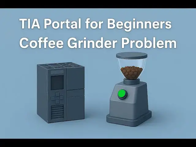
machine so let's look at the example
0:24
first coffee grinder timer when the
0:26
start button is pressed the grinder
0:28
should run for 10 30 seconds before
0:31
stopping automatically after stopping
0:34
the buzzer after stopping the buzzer
0:36
will turn on pressing stop button will
0:39
turn off the buzzer after 5 seconds so
0:42
for this example we will use a normally
0:45
open contacts for start button and stop
0:48
button and we will also use normally
0:51
Clos contacts for memory bits and we
0:55
will be also using some timers like TP
0:58
and T on so let's move to TI portal
1:02
where we will draw a ladder diagram for
1:06
machine this is the interface of TI
1:08
portal version 16 after adding the
1:11
device let's go to PLC tags
1:15
here PLC tags and then default tag table
1:19
I will double click on it so here we
1:22
need to add our inputs and outputs so
1:25
the first input is start button
1:30
and then we have one more input that is
1:36
button and then we have two outputs that
1:46
buzzer so the grinder is a is an output
1:50
device so its address will be Q 0.0 and
1:53
same will be with the buzzer so its
2:00
we will minimize this table and we will
2:03
go to program blocks I will double click
2:05
on it and then double click on Main
2:13
ob1 so here we will be drawing ladder
2:16
diagram I will zoom into
2:20
it and then I will add a normally open
2:23
contact here and then I will insert a
2:28
Quil so this normal open contact will be
2:31
start button and this coil will be
2:37
grinder so this grinder should run for
2:40
30 seconds for that we will use a timer
2:44
operation I will click on it and double
2:57
TP so the pret value for the the TP will
3:02
seconds so when start button is turned
3:04
on the grinder will operate for 30
3:07
second and after 30 seconds it will
3:11
stop and then I will open the branch
3:14
here and then I will add a
3:20
coil so this coil will represent
3:24
buzzer so after turning off the grinder
3:28
buzzer should turn on
3:36
buzzer will be t on will be used with t
3:41
on I will double click on T
3:46
on I'll click on okay and then the
3:49
preset value for t on will be 30
3:52
seconds so here when start button is
3:54
turned on the current will flow through
3:57
this this timer will start and it will
4:00
start uh immediately after turning on
4:02
the start button but this TP will turn
4:05
on it will allow the current to flow
4:07
through it as a result this grinder will
4:09
turn on so the grinder will uh run for
4:13
30 seconds and after 30 seconds the
4:15
current will not pass through this timer
4:17
this grinder will turn off but this t on
4:20
will allow the current to flow through
4:22
it after 30 seconds so when start button
4:24
is turned on it will wait for 30 seconds
4:27
and after 30 seconds the current will
4:28
flow through this and buzzer will turn
4:31
on and then we have one more button that
4:35
is a stop button so when it is turned on
4:37
I will insert a normally open contact
4:40
for store button so when Star button is
4:42
turned on the coil will turn on and this
4:47
Quil will be a memory bit so this will
4:49
be M 0.0 so this m 0.0 when top button
4:54
is turned on buzzer should turn off
5:01
Seconds so this m 0.0 should turn on
5:06
after 5 seconds so this m 0.0 the pre uh
5:11
the preced value for this t on will be 5
5:14
seconds and this m 0.0 will be used here
5:19
as normally Clos contact so this will be
5:26
0.0 so this m 0.0 will turn off the
5:29
Bowser so M 0.0 will turn on after 10
5:32
second after 5 Second when stop button
5:35
is pressed when stop button is pressed M
5:37
0.0 gets on after 5 Second as a result
5:40
this fer will turn on after 5 seconds so
5:54
simulation click on okay
6:30
finish and after that I will start
6:35
monitoring and with that I will switch
6:53
view here we need to create a new
6:55
project let's create a new
7:58
after that I will go to simulation
8:01
tables and simulation table
8:05
one I will right click here and load
8:16
TX after that I will need to start the
8:23
uh so as you can see here when I turn on
8:34
the grinder turns on and it remains on
8:40
seconds 12 13 14 the grindle will
8:44
operate for 30 second and after 30
8:47
second it will automatically
8:52
stop and after stopping the grinder the
8:57
start so the grinder stopped but the
9:00
buzzer turns on then we need to press
9:04
the stop button to turn off the
9:13
buzzer so when I turn on the stop
9:17
button when I turn on stop
9:20
button the buzzer doesn't uh turn
9:24
off immediately but it will stop for uh
9:30
seconds it was all about this example
9:33
thank you for watching