0:07
Hello everyone, myself Baras. In this
0:11
video I will discuss briefly about 4 to
0:16
20 millia based signals.
0:20
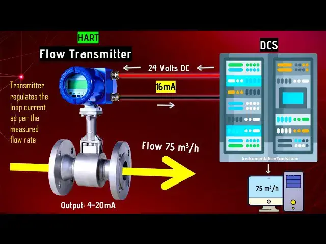
Let's say we have a flow transmitter.
0:24
And it is hotbased smart flow
0:30
It is configured with 0 to 100 m cube
0:36
It supports output 4 to 20 millia basin
0:42
We have a DCS system distributed control
0:48
Now this DCS system is connected with
0:50
this instrument using two wires.
0:54
This is the positive wire and this is
0:57
the negative. DCS uh provides 24 volts
1:01
DC power supply to the failed
1:07
This flow transmitter measures the flow
1:13
Let's say for example the flow is 0 m
1:16
cube per hour. There is no flow at all.
1:21
So the transmitter regulates the loop
1:25
accordingly as per the measured flow
1:30
What is the signal range? 4 to 20 millia
1:34
signal. The four represents lower range
1:38
value. The 20 represents upper range
1:43
Right now the flow is zero.
1:47
Then this flow transmitter regulates the
1:49
loop current to the 4 milliampere.
1:54
See the flow transmitter sending 4
1:59
The DCS measures this loop current and
2:03
then displays to the operator.
2:07
Okay. So on the operator computer it is
2:10
displaying 0 m cube per hour. So this is
2:13
the basic concept for a 4 to 20 millia
2:17
based instrument which is configured in
2:23
Let's say the flow increased to 25 m
2:30
Again the transmitter measures this flow
2:35
and updates the loop current
2:41
Now the transmitter sending 8 miampere
2:46
The DCS receives this 8 milliampere
2:50
and the DCS is already configured with
2:53
the flow transmitter details.
2:56
For example, the transmitter's range is
2:59
0 to 100 m cube per hour and its
3:02
equivalent signal is 4 to 20 miampere
3:05
signal. Accordingly, the DCS
3:09
uh converts this measured milliampere
3:12
into the equivalent flow rate and then
3:16
displays onto the computer graphics.
3:19
The computer graphics is 25 m cube per
3:24
Similarly, let's say the flow is
3:26
increased to 50 m cube per hour. Again
3:32
transmitter sends 12 milliampere signal
3:35
to the DCS system. The DCS converts this
3:39
12 milliampere into equivalent flow rate
3:41
and displays 50 m cube per hour
3:46
in the computer graphics.
3:49
Similarly the flow is increased to let's
3:51
say 75 m cube per hour and transmitter
3:56
sends 16 miampere signal to the DCS
3:59
system. Again DCS system updates this
4:03
value in the computer graphics. This
4:06
computer graphics nothing but operator
4:08
workstations or engineering
4:12
Let's say the flow reached maximum
4:17
100 m cube per hour. Then transmitter
4:20
updates this loop current again. The
4:23
maximum signal is 100 m cube per hour
4:26
flow signal. And what is the current
4:30
What is the maximum current signal? You
4:31
can see the 20 is the maximum signal in
4:34
this range. So the transmitter sends 20
4:37
milliampere signal to the DCS system and
4:40
DCS updates the flow rate on the
4:44
So this is the traditional 4 to 20
4:48
millia based instruments configuration
4:55
In the next video, I will discuss
4:58
briefly about heart protocol.
5:02
If you have any questions regarding this
5:05
video, please share with us using the
5:11
and please like our videos, share our
5:14
courses with your friends and social
5:19
Thank you. Thank you for your support.