0:05
We will connect the Productivity Mini
0:09
16DR to our computer running the
0:11
Productivity Suite software. An Ethernet
0:14
RJ45 communication link will be made to
0:16
our programmable logic controller. The
0:18
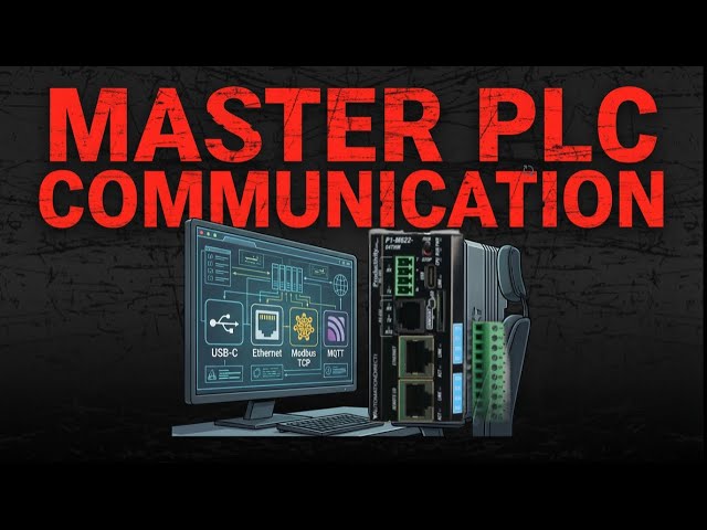
P1 M622 series packs six communication
0:21
ports into a standalone package smaller
0:23
than your hand. That's USBC programming,
0:26
dual Ethernet ports, RS232, RS485, and a
0:30
micro SD slot for data logging, all
0:32
without needing separate IO modules or
0:34
power supplies. Let's get started.
0:37
Detailed information contained in this
0:39
video can be found at acccca.ca.
0:42
A link has been put in the description
0:44
below. The website offers extensive
0:46
links, references, and coding samples,
0:48
making it a one-stop shop for all your
0:50
automation queries. accutomation.ca CA
1:02
mini PLC includes the following
1:07
One, micro SD slot. Two, USBC 2.0
1:11
programming port. Three, RS232 serial
1:17
Four, RS485 serial port terminal block
1:21
Five 10100 megabyte Ethernet port.
1:25
Six 1000 megabyte Ethernet port for
1:36
Connect our RJ45 Ethernet cable from the
1:39
Ethernet port on the Productivity Mini
1:44
to our network router or switch. Our
1:48
computer is also connected to the router
1:50
or switch on the same network.
1:54
Start the productivity suite software
1:56
package. Double click on the shortcut
1:58
icon on your screen or from the Windows
2:00
start button. All programs automation
2:02
direct productivity suite.
2:07
Call the productivity CPU connections
2:12
When you first start up the productivity
2:14
suite software, you will get the start
2:16
menu. Click on read the project from the
2:19
CPU. This will call up the CPU
2:23
You can also get to this window at any
2:25
time by one of the following three ways.
2:28
One, click the choose CPU icon in the
2:31
software's main menu.
2:35
Two, click choose CPU from the
2:37
application tools menu under control
2:43
Three, click choose CPU from the main
3:06
Click the IP4 connection in the CPU
3:11
You will notice we now have some
3:13
additional choices that we can change.
3:15
Click start blinking CPU run light.
3:19
This will start the run light on the
3:22
unit blinking. It is a great way to
3:25
ensure that we are communicating with
3:27
the correct PLC unit.
3:30
Click stop blinking CPU run light. The
3:32
run light will stop blinking.
3:36
Change IP address. Productivity Ethernet
3:43
Highlight the Ethernet connection type
3:45
in our CPU connections window. Click
3:48
change CPU IP all name. The change IP
3:51
address while CPU name window will now
3:55
Ensure that the Ethernet port is
3:57
selected. We will now change the
3:58
settings to the following. IP address
4:06
Subnet mask 255 255 255 0
4:12
default gateway 192 168 1 This is the
4:16
access to the internet.
4:18
See the following for a review of IP
4:20
addressing accutomation.ca.
4:23
What everybody ought to know about IP
4:27
The CPU name default is the model
4:29
number. This is P1 M62216DR.
4:33
We will leave this as is, but you could
4:35
change the name to something easier to
4:36
address in your automation project.
4:40
Click okay to save the changes made.
4:43
Notice that the IP address has changed
4:45
in our CPU connections window.
4:50
Connect to the PLC, establishing
4:52
Ethernet communication.
4:56
Click on the connect button.
4:59
This will select the Ethernet port we
5:00
want to use for programming the unit in
5:02
our CPU connections window.
5:08
We currently have no project in our CPU,
5:11
so a warning message is shown. Click
5:16
Our screen will now show that we are
5:17
connected the PLC's current mode and the
5:20
PLC's connection status.
5:23
The icon in the software's main menu
5:24
shows we are online and in stop mode.
5:28
The application tools menu under control
5:30
CPU also shows that we are online and in
5:34
The status bar at the bottom of the
5:36
screen under CPU will show our
5:38
connection type and the CPU name.
5:41
CPU the Ethernet connection 192 1681 156
5:51
If you are enjoying this video, please
5:53
hit the like button below. Keeping up
5:55
with all the latest automation
5:56
innovations can be difficult, so hit the
5:58
subscribe button. Remember to hit the
6:00
bell beside your subscription to receive
6:04
Establishing communication with our mini
6:06
PLC is straightforward.
6:11
P1 M622 16DR communication capabilities.
6:18
The mini PLC Ethernet port supports
6:20
Modbus TCP client connections. 16 server
6:23
devices. Modbus TCP server connections
6:25
16 client devices Ethernet- IP scanner
6:28
32 adapters Ethernet- IP adapter four
6:32
scanners with eight connections per
6:34
device custom protocol over Ethernet
6:36
CPoE ProNet for productivity to
6:38
productivity communication outgoing
6:42
The remote IO Ethernet port supports GS
6:45
drive connections up to 16 drives.
6:48
Protostcp couplers up to four P1 RX
6:51
remote slave modules up to four PSAMC
6:57
The serial ports support RS232 Modbus
6:59
RTU master slave ASI custom protocol
7:02
RS485 multi-drop Modbus RTU networks up
7:05
to 1,000 meters ASKI communication.
7:08
Next time we will write our first
7:10
program and transfer it to the
7:11
Productivity Mini PLC P1 M62216DR.
7:19
The Productivity Mini PLC series from
7:21
Automation Direct and specifically the
7:25
is a compact powerhouse that packs
7:27
serious capability into a surprisingly
7:31
To learn more, click here. Click here to
7:33
build digital twins of 3D virtual
7:35
machinery. Test control logic and learn
7:37
automation without expensive hardware
7:39
using machine simulator.