0:07
hello everyone myself
0:10
badas in this video I will discuss about
0:15
interlock and a simple example
0:23
interlock see interlock is a safety or
0:28
mechanism that pre vents certain actions
0:33
unless specific conditions are met see
0:39
this is a basic definition of an
0:42
interlock interlocks are very important
0:45
in Industries generally we will use
0:48
these interlogs such that we can prevent
0:53
some safety related accidents see these
1:02
the first one is machine guard a machine
1:06
won't run if its safety door is open for
1:13
machine and the operator given the start
1:17
command for the machine but its safety
1:21
door is in open condition instead of
1:25
close when there is an interlock for
1:28
this safety door is there
1:30
then even though the operator given the
1:33
start command but the mission will not
1:37
start because the door sensor interlock
1:44
motor okay the program will not be
1:48
active or will not activate the output
1:51
command even though the operator given
1:54
the start command because of the safety
2:01
another example is conveyor
2:04
belt a conveyor belt won't start unless
2:09
all emergency stop buttons are
2:13
released for every machine motor pump
2:20
Etc all the machines in
2:23
Industries will have the emergency stop
2:27
buttons the default state of the stop
2:31
buttons must be in release State
2:34
okay then only the machine will
2:37
start this is also one of the basic
2:41
interlock example okay now we will
2:44
discuss one example we'll go to the
2:48
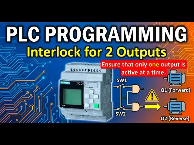
example the example is interlock for two
2:52
outputs develop a PLC program to control
2:56
a motor forward and reverse
3:00
rotation using two switches s W1 and S
3:06
W2 there is a motor the motor
3:11
output either it can rotate in forward
3:14
Direction when the output q1 is in on
3:18
or it can rotate in Reverse Direction
3:22
when the output Q2 is in on state these
3:26
two outputs are directly controlled
3:29
using two switches if switch one is on
3:34
then the motor rotates in forward
3:36
direction that means q1 will be on if
3:40
switch 2 is in on state then the motor
3:44
rotates in Reverse direction that means
3:53
that only one output is active at a time
3:58
okay the motor can rotate either in
4:01
forward direction or in Reverse
4:04
Direction definitely it will not rotate
4:07
in both directions at a time if you give
4:10
such type of command then the motor will
4:13
be damaged so we have to prevent these
4:17
type of Damages using
4:20
interlocks okay if both switches are on
4:24
at a time then all outputs is in off
4:30
when switch one is on q1 will be on when
4:33
switch two is on Q2 will be on if In
4:36
Case by mistake operator presses both
4:40
switches at a time then all outputs
4:43
should be in off State so this is a
4:46
basic interlock for two
4:48
outputs now open your
4:52
software now take two
4:57
inputs and I will take I3 and I4 you can
5:06
input add the comment also I3 is my
5:12
one and I4 is my switch to
6:10
now for interlock purpose I will
6:14
use basic functions end gate
6:19
okay take two end blocks and give the
6:23
command the top one is my
6:30
and second one is my end
6:43
two now connect first end gate output
6:47
with q1 and second end gate output with
6:53
Q2 now connect switch one input
6:57
3 to the first first input of
7:02
endgate similarly connect switch to with
7:06
first input of second end
7:10
gate now connect switch one with the
7:14
last input of second end
7:18
gate similarly connect switch to with
7:22
the last input of first end
7:28
overlapping so that we will have better
7:32
Clarity okay now what I will do I want
7:36
to add one not gate to the second input
7:40
of both the end Gates either you can use
7:44
the not block from the basic functions
7:49
or what I will do I will just do this
7:53
simple double click of the second
7:57
input then one bubble will appear
8:00
this means the input is inverted the
8:03
knot is added similarly I will press two
8:08
times in the second handgate
8:14
also not get is added this is the
8:37
hardware and download the
8:42
program if you don't have the PLC
8:45
Hardware with you just do the simulation
8:51
logic I suggest you to open your PLC
8:54
software and practice the program
8:57
instead of Simply watching the videos
9:00
you will not remember after some time if
9:02
you only watch the videos you must
9:06
practice the lesson or examples or
9:10
assignments or tasks you must perform
9:14
hands and now I go to the online
9:24
mode select the IP and click
9:30
now when I press the switch one when I
9:34
turn on the switch one M forward will be
9:37
active that means q1 will be on see
9:41
switch one is on the first endgate two
9:44
inputs are on on state the first input
9:48
is switch one it is in on State and the
9:50
second input is switch
9:52
two but the not is added that is why
9:56
switch to is in off State and with
9:58
because of not it is in on and endgate
10:03
both inputs are in on state the output
10:09
on now what I will do I will turn off
10:13
one and turn on switch
10:18
happens the second end gate output is on
10:22
that is why output Q2 is on that means
10:25
motar is rotating in Reverse Direction
10:29
you can see the second and gate inputs
10:32
are in on state that is why output is in
10:35
on state let's suppose in this case I
10:38
will turn on the switch one that means
10:42
both switches are on at a
10:44
time in this case the outputs are in off
10:48
State both are in off Swit
10:51
State the not BL gate are not input of
11:00
making the outputs in off State
11:03
simple this is very simple
11:06
logic using and and not blocks okay
11:12
practice this logic and one more simple
11:15
task for you is this is a interlock of
11:19
two outputs now consider interlock of
11:23
three outputs you have three inputs
11:26
switch one switch two switch three and
11:29
you have three outputs q1 Q2
11:33
Q3 switch one is when switch one is in
11:36
on state q1 will be on when switch two
11:39
will be in on state Q2 will be on when
11:43
switch three is in on state Q3 will be
11:47
okay if two switches or three switches
11:52
are on at a time then all outputs must
11:59
okay now now try to solve this logic and
12:04
us how you implemented this logic
12:07
remember this second task is similar to
12:10
the same program which is we discussed
12:12
here I just added one more input and one
12:15
more output okay thank you I will meet
12:19
you in the next video