0:05
Hello everyone, welcome to automation
0:08
community. Today in this video we are
0:11
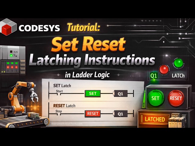
going to discuss about set coils, reset
0:17
So let's start. I will open cortices.
0:30
Let's create a new project.
0:34
Select template as standard project and
0:38
Select the PLC programming as ladder
0:41
logic diagram and click on okay.
0:48
Let's go to PLC programming and here we
0:51
will insert a normally open contact and
1:00
Okay. And I will insert a normal coil
1:04
here and this will be output
1:10
Okay. So here what will happen when
1:13
input one gets on output one gets on and
1:15
when we turn off input one output one
1:22
when we use a set coil when input gets
1:25
on that coil gets on and when the input
1:28
gets off the soil remains on. So we will
1:33
use the set coil here in another
1:35
network. So we'll insert network below
1:38
and we will insert a coil here. Sorry, a
1:40
normally open contact and this will be
1:45
okay and we'll use a set coil here.
1:49
Insert set coin and this will be output
1:54
to so let's simulate it first. Let's
2:03
and then go to online and start
2:06
simulation. After that I will log in
2:16
So when I turn on input one, let's debug
2:20
it. It values. Output one gets on. And
2:24
when I turn it off, when I turn off
2:30
output one also gets off. But when you
2:33
use a set coil, what will happen? when I
2:36
turn on the input when input two is on
2:43
then output two gets on and when I turn
2:48
when I turn it off the output two
2:51
remains on. This is the use of a set
2:54
coil. So set coil remains set remains on
2:58
when the input gets on and then off it
3:01
remains on. So to to to
3:05
turn it off to turn it off we use reset
3:08
coils. So we will use that we will stop
3:12
the simulation here. We will log out and
3:16
then click here online go to
3:19
simulations. So we'll insert one more
3:21
network below and we will use a normally
3:25
open contact and this will be input
3:31
Okay. And then we will use a reset coil.
3:34
So to turn off this output two, we will
3:38
use one more uh coil that is a reset
3:40
coil and its address will be same as
3:43
that uh we have used for output two. So
3:47
this will be output 2.
3:51
So let's uh log here. Before login we
3:55
will go to online and start simulation.
4:06
After that we will start and you can see
4:10
here this output two is true because we
4:13
have already previously uh turned input
4:16
two as on and then turned off. So to
4:19
turn off this output two we are using
4:21
one more input that is input three and
4:24
with that we have used a reset coil.
4:27
This reset coil will be used to reset
4:29
this output two. So let's see what will
4:32
happen when I turn on input three. We
4:35
will go to debug and write values. You
4:38
can see the output uh two gets off. So
4:42
when I turn on input two,
4:45
when I turn on input two, let's debug
4:53
And to turn off the uh this output two
4:56
when I turn off input two
5:00
output two remains on. This is the use
5:02
of set coil. So this output two remains
5:06
on even if when we turn off the input.
5:09
So to turn off this output two we will
5:12
use input three and with that we will
5:14
use the reset coil and the address of
5:16
this reset coil will be same as that of
5:19
output two. So we'll use input three
5:22
when we will turn it on we'll go to
5:25
debug and write values this output two
5:28
gets off. So I will stop this log out
5:36
So in this way we will be using set
5:38
coils and reset coils. And now we will
5:41
discuss about latching. So latching is
5:44
similar to this set coil. So when input
5:47
is on output gets on and when input gets
5:50
off output remains on. So this is a
5:53
method of doing that. But we will now
5:55
discuss one more method of you know
5:57
putting the setting the value of the
5:59
output as on even if when we turn off
6:02
the input. So I will insert a network
6:05
here below and I will insert a normally
6:09
open contact that is input
6:13
port. Okay. And then we will insert a
6:16
coil, a normal coil in this case for
6:19
latching. And this will be output three.
6:26
Okay. And this output three, we'll use
6:30
this as here. So here we will insert a
6:34
contact parallel to input four. And the
6:38
address of this normally open contact
6:40
will be same as the address which we
6:42
have to latch which we have to put on
6:46
even when we turn off the input. So this
6:53
So what happens is that when input gets
6:58
when input four gets on the signal will
7:01
pass through this. As a result this
7:03
output three gets on. Okay that's fine.
7:06
But when we turn off the input 4, the
7:09
signal will not pass through this. But
7:11
the signal will pass through this
7:14
contact. So previously when we have
7:17
turned on the input four, output three
7:19
got on and the state of output 3 is
7:22
true. And when the out when the state of
7:24
output 3 is true, so is the state of
7:27
this output three as contact. So this is
7:29
also true. The signal is also flowing
7:32
through this. And when we turn it off,
7:34
when we turn off input 4, the signal
7:38
passes through this and puts the output
7:41
three on. It will remain on. So we will
7:45
login here. Before login, we will go to
7:48
online and start simulation. And now we
7:50
can login. Okay. And then let's start.
7:55
So when I turn on input four, go to
7:59
debug and write values, output three
8:02
gets on. And when I turn it off, when I
8:05
turn off input four, go to debug and
8:08
write values, output three remains on.
8:11
How this output three is on, this output
8:14
three is on, the signal passes through
8:16
this and leaves the output three on even
8:19
if when we turn off the input four.
8:24
It was all about this example. Thank you