0:11
hello everyone welcome to automation
0:14
Community today in this video we are
0:17
going to discuss an example which will
0:22
coolant so let's look at the example
0:26
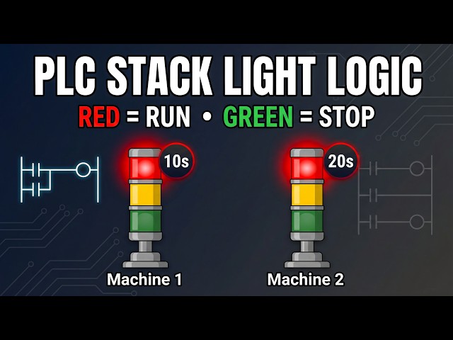
first machine indicator lights suppose
0:30
you have a warning light system to
0:32
indicate whether a machine is running or
0:34
not two red lights will indicate
0:37
individual machine 1 and Machine 2
0:39
running status these machines operate
0:42
for 10 second and 20 second respectively
0:46
two green lights will indicate when
0:49
operating that means there will be a
0:52
start button that will start the
0:55
machines and when machine one is running
0:58
red light one will turn turn on and
1:01
green light two will turn on and then
1:03
after that machine two will turn on with
1:06
that red light two will be on and green
1:09
light one will be also on so for this
1:13
example we will use normally open
1:15
contacts and some memory bits we will be
1:18
also using some timers like TP and T on
1:21
so let's move to TI portal where we will
1:24
draw a ladder diagram for this
1:26
example this is the interface of TI
1:29
portal version 16 so firstly we will go
1:33
to PLC tags and default tag table so
1:38
here we need to add our inputs and
1:40
outputs so the first input is
1:44
button and then we have some outputs
1:49
machine one then we have Machine
1:55
2 so the address for the the outputs
1:58
will start with q and then
2:05
0.0 and then we have red light
2:12
red light 2 and then we have green light
2:17
one and then we have green light
2:21
two so these are our inputs and outputs
2:25
after that you'll go to program blocks
2:27
double click on Main ob1
2:31
so here we will be drawing the ladder
2:32
diagram so I will zoom into it like this
2:35
so firstly I will insert a normally open
2:37
contact and a coil and this normally
2:41
open contact will be the start button
2:43
and the coil will be a memory bit that
2:48
0.0 and this m 0.0 will be last here so
2:52
I will open the branch add a normally
2:54
open contact and close so this will be M
2:58
0.0 and and after that we will use this
3:01
m 0.0 here I will add a normally open
3:08
0.0 and we will use this m 0.0 to turn
3:11
on two coils so I will open the branch
3:14
here and add one more coil so this
3:18
coil will represent M 0.1 and this coil
3:26
0.2 so this m 0.1 will be used to turn
3:30
on machine one red light one and green
3:33
light two so machine one will be on for
3:35
10 seconds so we will use a timer
3:40
TP and the preset value for the TP will
3:47
seconds and then this m 0.0 M 0.2 will
3:52
be on after 10 seconds so there will be
3:55
a delay of 10 seconds so we will we have
3:59
we are using here t on and the preset
4:01
value for t on will be 10 seconds and
4:04
this m 0.2 will be used for to turn on
4:07
Machine 2 red light two and green light
4:10
one and Machine 2 remains on for 20
4:13
seconds for that we will use a TP here
4:17
and the preset value for TP will be 20
4:19
seconds so now we can use M 0.1 here as
4:24
normally open contact that remains on
4:26
for 10 seconds and that will
4:33
make and then I will again open the
4:37
branch and add a coil so this m 0.1 will
4:41
make machine one on for 10 seconds with
4:44
that red light one and green light two
4:46
will also be on so this coil will be for
4:50
machine one and then red light
4:56
two so these things machine one red
5:00
light one and green light two will be on
5:02
for 10 seconds and after that we will
5:05
use one more normally open
5:12
m02 so this m 0.2 will be used to turn
5:16
on Machine 2 for 20 seconds with that
5:20
red light two and green light one will
5:22
also be on so I will insert three coils
5:24
one by one for Machine 2 open the branch
5:28
add a coil for Red Light 2
5:30
and then open the bran and a coil for
5:33
green light one so this will be Machine
5:40
two and then green light
5:43
one so as you can see here when start
5:46
button is pressed and released M 0.0
5:49
gets through and when M 0.0 gets through
5:51
M 0.1 gets on for 10 seconds and when M
5:55
0.1 gets on for 10 seconds machine 1
5:58
gets on for 10 10 seconds with that red
6:00
light one and green light two also
6:02
becomes on for 10 seconds and after 10
6:06
seconds this m 0.2 gets on for 20
6:09
seconds and when M 0.2 gets on for 20
6:12
seconds this machine two works for 20
6:15
seconds and in those 20 seconds red
6:17
light two and green light one also
6:20
remains on so we will start the
6:47
finish after that I will start the
6:55
monitoring and then I will switch the
7:03
let's create a new project here
7:39
go to simulation tables and simulation
7:41
table one right click
7:44
here and load project
7:46
a so as you can see here when start
7:51
pressed and then release you can see
8:03
on after that machine 2 turns
8:10
on and it will remain on for 20 seconds
8:14
as you can see 1920 and after 20 seconds
8:17
these Machine 2 red light two and green
8:23
off so when I turn on start button as
8:27
you can see here M 0.0 get gets true and
8:30
with that this m 0.1 gets through for 10
8:33
seconds and with that machine one red
8:35
light one and green light two gets on
8:37
and after 10 seconds it start working
8:39
and M 0.2 gets through for 20 seconds
8:42
with that machine 2 red light two and
8:44
green light one gets on and it remains
8:47
on for 20 seconds and after that as you
8:50
can see here after that after 20 second
8:53
16 17 18 19 20 and 0.2 gets off and with
8:58
that this Machine 2 red light 2 green
9:01
light one also gets off it was all about
9:04
this example thank you for watching