Up next in 10

Master P1-M622-16DR Mini PLC – Timer Instructions!⏱️ on the Productivity PLC. Step-by-step tutorial with real-world examples.
Almost every PLC program includes a timer instruction. This video showcases the implementation of a "timer in PLC" using Productivity Suite software for a Productivity Mini PLC, focusing on the Simple Timer and Timer instructions. We build on our "motor control circuit" to demonstrate practical applications of "PLC programming" and "ladder logic". Learn how to configure these essential "PLC timer" functions with real-world tips.
📖 FULL WRITTEN TUTORIAL + DOWNLOADS
https://accautomation.ca/p1-m622-16dr-mini-plc-timer-instructions-⏱️/
⏱️ Video Chapters
0:00 P1-M622-16DR Mini PLC – Timer Instructions! ⏱️
0:53 Timing Diagrams – Productivity Timer
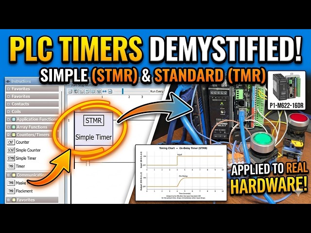
1:36 Simple Timer (STMR) – On Delay Timer
5:57 Simple Timer (STMR) – Off Delay Timer
9:19 Timer (TMR) – Up/Down Timer with Reset
13:39 Retentive vs. Non-Retentive Timer Values
14:45 Summary – Choosing the Right Timer
📚 WHAT YOU'LL LEARN
✅ P1-M622-16DR Mini PLC – Timer Instructions!⏱️ step by step on the Productivity PLC
✅ Hardware wiring and I/O connections
✅ Timer instructions (TON, TOF) in ladder logic
✅ Counter instructions and count-based control
Show More Show Less View Video Transcript
0:03
Almost every PLC program includes a
0:05
timer instruction. The Productivity mini
0:07
PLC P1M-622 16 DR offers several timer
0:11
instructions.
0:12
We discussed the time coil TMC and
0:14
flasher coil FLS in our last post as
0:17
part of our discussion of contacts and
0:18
coils.
0:19
In this session, we will review the
0:21
instructions for the simple timer STMR
0:23
and timer TMR in the Productivity Suite
0:25
software.
0:26
We will build on our start-stop motor
0:28
circuit from earlier in this series and
0:30
demonstrate practical timer examples
0:31
that you can use in real programs.
0:34
Let's get started.
0:36
Detailed information contained in this
0:38
video can be found at accautomation.ca.
0:41
A link has been put in the description
0:43
below. The website offers extensive
0:45
links, references, and coding samples,
0:47
making it a one-stop shop for all your
0:49
automation queries.
0:50
Once again, that is accautomation.ca.
0:54
Timing diagrams, Productivity timer.
0:57
Timers are used in most PLC programs.
1:00
Before writing a single rung of timer
1:01
logic, it is important to understand the
1:03
timing chart, also called a timing
1:05
diagram.
1:06
A timing chart is a visual
1:08
representation of how inputs and outputs
1:10
relate to each other over time.
1:13
It shows you exactly when an output
1:15
should turn on and off relative to its
1:16
input, which determines which type of
1:18
timer you need.
1:20
We have covered timing charts in detail
1:21
in the following post, The Secret of
1:23
Using Timers.
1:25
Understanding the timing chart first
1:27
will save you a great deal of
1:28
troubleshooting time later.
1:31
Always sketch your timing chart before
1:32
building your rungs.
1:37
Simple timer STMR, on-delay timer.
1:40
The simple timer STMR is the most
1:42
straightforward timer in the
1:43
Productivity Suite.
1:45
It is found in the timer counter
1:47
category of the instructions list. The
1:49
STMR has two operating modes, on-delay
1:51
and off-delay.
1:53
On-delay, the output turns on after the
1:55
input has been on continuously for the
1:57
preset time.
1:59
If the input turns off before the timer
2:01
expires, the current value resets to
2:03
zero and the timer restarts when the
2:05
input turns on again.
2:07
Setting up the simple timer using the
2:09
structure.
2:11
When you add an STMR to your ladder, you
2:13
will be prompted to enter the addresses
2:14
individually or use the structure
2:16
option.
2:17
Select new structure, give it a name.
2:20
For this example, we will use simple
2:21
timer one. Using the structure
2:23
automatically creates the following
2:24
tags.
2:27
Simple timer one preset, 32-bit integer,
2:29
the time value the timer counts to.
2:32
Simple timer one current, 32-bit
2:34
integer.
2:35
The current accumulated time value.
2:38
Simple timer one done, Boolean, turns on
2:41
when current reaches preset.
2:44
Under the tag definitions, set the
2:46
preset value to memory retentive so it
2:48
survives a power cycle and enter an
2:49
initial value of 100.
2:52
The STMR time base is 100 milliseconds,
2:55
0.1 seconds per count, so 100 counts
2:57
equals 10.0 seconds.
3:02
Practical example with the start-stop
3:03
circuit.
3:06
Now add the STMR instruction to a new
3:08
rung below your start-stop motor circuit
3:10
with DI0.1.1.3,
3:12
a switch input, as the rung condition.
3:15
Add a rung below the STMR instruction.
3:18
Place a NO contact using simple timer
3:20
one done as the tag and wire it to an
3:22
out coil on DO001.1.2,
3:26
a second relay output, an indicator
3:28
light, for example.
3:51
Note, before testing our circuit, call
3:53
up the tag database. We can turn on the
3:55
forcible bits for the inputs and
3:57
outputs.
3:58
This will allow us to test all of our
4:00
inputs and outputs on the CPU unit.
4:55
Highlight the two new rungs and right
4:57
click.
4:59
Select the monitor and data view. In the
5:01
monitor and data view window, select
5:02
create new tab. Select okay.
5:06
We can now monitor our new rungs.
5:08
When DI0.1.1.3 is turned on, the timer
5:11
begins counting. After 10 seconds, the
5:12
done bit energizes and DO0.1.1.2
5:15
turns on.
5:16
If DI0.1.1.3
5:18
turns off before the 10 seconds expire,
5:21
the current value resets to zero. The
5:22
output remains off.
5:25
This is a classic on delay application
5:28
used whenever you want to delayed start.
5:30
A conveyor that begins moving 10 seconds
5:32
after a start signal, a warning horn
5:34
that sounds after a door has been open
5:36
for a set time, or a motor that needs a
5:38
warm-up delay before a downstream
5:39
process begins.
5:57
>> Simple timer STMR off-delay timer.
6:00
The off-delay timer keeps the output on
6:02
for the preset time after the input
6:04
turns off.
6:06
The output is on while the input is on
6:08
and remains on for the preset duration
6:11
after the input drops.
6:13
Setting up the off-delay.
6:16
Add a second STMR instruction, select
6:18
new structure and name it simple timer
6:20
two.
6:31
This creates the same three tags.
6:34
Simple timer two preset 32-bit integer.
6:38
Simple timer two current 32-bit integer.
6:42
Simple timer two done Boolean.
6:45
Set the preset to memory retentive with
6:47
an initial value of 1,000, 10.00
6:50
seconds.
6:52
In the STMR instruction block, change
6:54
the timer mode from on-delay to
6:55
off-delay.
6:57
How it works. When the rung input DI
6:59
0.1.1.4
7:01
turns on, the simple timer two done
7:03
output bit immediately turns on.
7:06
When DI 0.1.1.4
7:08
turns off, the timer begins counting.
7:10
After 10 seconds, the done bit turns
7:12
off. The timer's current value resets
7:15
and is ready for the next cycle.
7:18
Practical example with the start-stop
7:20
circuit. Imagine you want the motor or a
7:21
fan to continue running for 10 seconds
7:23
after the operator presses stop.
7:26
A fan motor run-down delay is allowed to
7:28
allow for cooling before fully stopping.
7:30
Wire the motor's running status [music]
7:31
DO 0.1.1.1
7:33
as the run condition for the off-delay
7:35
STMR.
7:38
Drive a second coil from the done bit
7:40
that keeps a downstream device
7:41
energized.
7:43
When the motor stops, the downstream
7:44
device stays on for [music] the
7:46
10-second run-down period.
7:49
Tip: The on delay and off delay modes of
7:51
the STMR can each be demonstrated
7:53
clearly on a timing chart. Draw the
7:55
input line and the output line before
7:57
writing your rungs. The relationship
7:59
between them will tell you exactly which
8:00
mode you need.
9:19
Timer TMR, up-down timer with reset.
9:22
The timer TMR instruction provides more
9:25
flexibility than the simple timer. It
9:27
supports independent up and down count
9:29
inputs, a separate reset input, a
9:31
selectable time base, and four
9:33
comparison output bits.
9:35
This makes it ideal for applications
9:37
where you need to track elapsed time in
9:39
multiple directions or trigger outputs
9:41
at specific time thresholds.
9:44
Setting up the TMR using the structure.
9:47
Add a TMR instruction from the timer
9:49
counter category. Select use structure
9:51
and name it timer one.
9:54
Set the time base to seconds. This
9:56
creates the following tags.
9:58
Timer one preset, a 32-bit integer.
10:01
The target value for comparison.
10:04
Timer one [music] reset, 32-bit integer.
10:06
The value the current value is set to
10:08
when reset is triggered.
10:10
Timer one current, 32-bit integer. The
10:13
current accumulated time in the selected
10:14
time base.
10:16
Timer one less, Boolean.
10:18
On when current is less than preset.
10:21
Timer one equal, Boolean. On when
10:23
current equals preset.
10:25
Timer one greater, Boolean.
10:27
On when current is greater than preset.
10:30
Set preset, reset, and current to memory
10:32
retentive. Set the preset initial value
10:34
to 20 20 seconds.
10:37
Time up input. Wire DI0.1.1.5
10:41
as the time up input. When DI0.1.1.5
10:44
is on, the timer counts up at the time
10:47
base rate, 1 second per count.
10:49
The current value increases toward the
10:50
preset.
10:52
Time down input. Wire DI0.1.1.6
10:56
as the time down input.
10:57
When DI0.1.1.6
11:00
is on, the timer counts down at the time
11:02
base rate. The current value decreases.
11:05
Important. When both time up and time
11:08
down inputs are on simultaneously, the
11:10
timer does not count in either
11:11
direction.
11:12
>> [music]
11:13
>> It holds its current value until one
11:14
input drops.
11:16
Reset input. Wire DI0.1.1.7
11:19
as the reset input. When DI0.1.1.7
11:23
is activated, the timer's current value
11:25
is set to the reset value, in our case,
11:27
zero.
11:29
This clears the accumulated time and
11:30
returns the timer to its starting state.
11:33
Using the comparison outputs,
11:37
the three Boolean output bits, less,
11:39
equal, and greater, give you three
11:41
trigger points from a single timer.
11:44
For example, use timer one less to keep
11:47
a green indicator light on while the
11:48
timer is still below the preset, process
11:50
running normally.
11:52
Use timer one equal to trigger a single
11:55
scan event when the timer hits exactly
11:57
20 seconds.
11:59
Use timer one greater to energize an
12:01
alarm output if the process has run past
12:03
the expected time.
12:06
Practical example with the start-stop
12:07
circuit.
12:09
Add the TMR to your program with the
12:11
motor output, DO 0.1 1.1, as the time up
12:14
run condition.
12:16
The timer will now track exactly how
12:18
long the motor has been running.
12:20
Wire timer one greater to an output coil
12:22
on DO 0 1.1.4,
12:25
an alarm light that turns on if the
12:27
motor has been running for more than 20
12:29
seconds without an operator reset.
12:31
Wire DI 0 1.1.7, a reset push button, to
12:34
clear the accumulated time when the
12:36
operator acknowledges the alarm.
12:39
This gives you a basic run time exceeded
12:41
alarm, a practical pattern used in many
12:43
real industrial applications.
12:46
If you are enjoying this video, please
12:47
hit the like button below. Keeping up
12:49
with all the latest automation
12:50
innovations can be difficult, so hit the
12:52
subscribe button.
12:54
Remember to hit the bell next to your
12:55
subscription to receive notifications.
13:40
>> Retentive versus non-retentive timer
13:42
values.
13:44
One important decision when configuring
13:46
any timer in the Productivity Suite is
13:48
whether to make the preset and current
13:49
values memory retentive.
13:51
A retentive tag retains its value
13:53
through a power cycle. The value is
13:55
stored in battery-backed memory and
13:57
restored on power up.
14:00
A non-retentive tag resets to its
14:01
initial value on every power cycle.
14:05
For the preset, retentive is almost
14:06
always the right choice.
14:08
You don't want your 10-second delay to
14:09
become 0 seconds after a power
14:11
interruption.
14:13
For the current value, retentive is
14:15
useful when you need to track
14:16
accumulated time across power cycles.
14:20
For example, a maintenance interval
14:22
timer that should not reset just because
14:24
the panel lost power briefly.
14:27
Non-retentive is appropriate when the
14:29
timer should always start fresh on power
14:31
up, for example, during a startup delay.
14:34
The P1M622-16DR
14:37
has on-board battery-backed memory to
14:38
support retentive tags. This is covered
14:40
in detail in the user manual, chapter 1,
14:43
getting started.
14:45
Here is a summary chart on choosing the
14:47
right timer.
14:51
The FLS flasher coil and TMC timed coil
14:54
were covered in the contact and coil
14:56
instructions post.
14:58
The STMR and TMR are the dedicated timer
15:00
instructions for more precise time-based
15:02
control.
15:04
Next time, we will look at counter
15:05
instructions in the Productivity mini
15:07
PLC P1M622-16DR.
15:11
Many PLC manufacturers offer a range of
15:13
hardware and software. All programmable
15:15
logic controllers share similar basic
15:17
features.
15:18
Once you are familiar with the basics of
15:20
the PLC, you will learn the specifics of
15:22
the controller you will be programming.
15:24
This is the easiest way to learn about
15:26
PLC programming. Click here to see how I
15:28
would approach learning about basic
15:29
PLCs.
15:31
Click here to see how you can program
15:33
for free with the ACC PLC simulator with
15:35
3D scenes you can program.
#Jobs & Education
#Factory Automation