Up next in 10

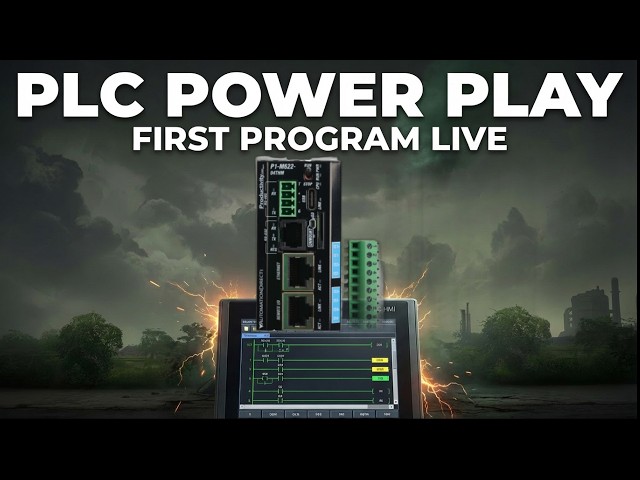
Master your first Productivity Mini PLC program! Stop struggling with ladder logic - finally understand how to create professional start-stop circuits.
📖 FULL WRITTEN TUTORIAL + DOWNLOADS
https://accautomation.ca/p1-m622-16dr-mini-plc-first-program-start-stop-motor-circuit
⏱️ TIMESTAMPS
0:00 - Introduction - P1-M622-16DR Mini PLC First Program
1:06 - Start New Project in Productivity Suite
1:52 - Choose CPU - P1-M622-16DR Mini PLC
2:39 - Tag Database Configuration
3:38 - Creating Ladder Logic Task
4:42 - Programming Start-Stop Motor Circuit
7:28 - Saving the Program
8:07 - Transfer Project to CPU
📚 WHAT YOU'LL LEARN
✅ How to create your first program on the P1-M622-16DR Mini PLC
✅ Setting up tag database with custom names for inputs and outputs
✅ Programming a complete start-stop motor circuit with sealing contact
✅ Transferring and saving projects in Productivity Suite software
Show More Show Less View Video Transcript
0:03
We will now create our first program on
0:04
the Productivity Mini PLC P1 M622 16DR.
0:10
Last time we connected the mini PLC with
0:12
our computer running the Productivity
0:14
Suite software. An Ethernet RJ45
0:17
connection was established to our
0:18
programmable logic controller. We will
0:20
now create our first program for our
0:22
Productivity Mini PLC. Our program will
0:25
be a simple start stop circuit for a
0:27
motor. Here's a post that will explain
0:28
the logic behind our program circuit.
0:31
Accutomation.ca.
0:33
How to make a start stop jog circuit in
0:34
a PLC. The P1 M6226DR
0:38
features eight built-in 24Vts DC syncing
0:41
inputs and eight relay outputs.
0:42
Everything you need for this first
0:44
program right in the compact CPU itself.
0:47
Let's get started. Detailed information
0:48
contained in this video can be found at
0:50
accccclautomation.ca.
0:53
A link has been put in the description
0:54
below. The website offers extensive
0:56
links, references, and coding samples,
0:58
making it a one-stop shop for all your
1:00
automation queries. accutomation.ca.
1:06
Start a new project, mini first program.
1:10
Start the productivity suite programming
1:11
software from the desktop icon or the
1:13
Windows start menu. All programs,
1:16
automation direct, productivity suite,
1:18
productivity suite. Our start
1:20
productivity window will now appear.
1:22
Select read the project from the CPU. As
1:25
before, it will present the options for
1:26
our communication.
1:29
We will select our Ethernet connection
1:31
to the PLC. This will give us a warning
1:33
because we currently do not have a
1:35
program in the PLC. Select connect.
1:39
We will receive error messages because
1:41
there is currently no program in the CPU
1:43
of our Productivity P1 Mini. Select okay
1:46
to acknowledge the error messages. We
1:48
are now connected to our PLC.
1:52
Choose CPU mini PLC first program.
1:56
Select the new project icon on the menu
1:58
options at the top of the screen. You
2:00
can also use the main menu and select
2:02
new project. File, new project.
2:06
The choose CPU window will now appear.
2:08
This will allow us to select the
2:10
hardware for our automation project.
2:13
Select P1 M622 M16DR. This is our
2:16
productivity mini PLC with 8DC inputs
2:19
and eight relay outputs. Select
2:20
continue.
2:26
A new task program will now appear under
2:27
the tasks heading in the run every scan
2:29
folder. This is located in the task
2:31
management. The new task is
2:32
automatically displayed and currently
2:34
shows as a series of end statements.
2:39
The tech database mini PLC first
2:41
program.
2:43
We reference our physical inputs and
2:45
outputs through our tag database. This
2:47
is automatically done when we configure
2:48
our hardware. Default names were
2:51
generated and given to the integrated IO
2:53
points. Select tag database under the
2:54
right program heading in the application
2:56
tools. Alternatively, you can use the
2:59
main menu. Choose edit g tag database
3:02
selection. The tag database will show us
3:03
a list of all of the assigned bits in
3:05
the CPU. These assigned areas can be
3:08
automatic or manually generated. To view
3:10
the physical inputs and outputs we
3:12
assigned when configuring the system,
3:13
scroll through all the tags. Another way
3:16
is to select only discrete inputs and
3:18
discrete outputs to display. We will now
3:20
only see our systems inputs and outputs.
3:23
For the P1 M62216DR
3:26
mini PLC, the automatic assignment can
3:28
be read as follows. DO1.1.1
3:31
discrete output system 0 base 1 slot one
3:34
bit location 1. So the first input on
3:37
our mini PLC would be DI0.11.1.1
3:40
[music]
3:41
discrete input system 0 base 1 slot one
3:44
bit location 1. The P1 M62216DR
3:48
has inputs DI0.1.1
3:51
through DI0.11.8
3:53
and outputs DO0.11.1.1
3:55
through DO0.11.8.
3:58
Under the editor in the tag database,
4:00
you will see several different columns.
4:02
The first one is name. Double clicking
4:04
the current default name lets you enter
4:06
a new one. We will name the first two
4:07
inputs as start and stop. The first
4:09
output will be named motor. The inuse
4:12
column indicates whether this tag is
4:13
used in your program or tasks. The
4:16
forcible selection for the tag
4:17
determines whether we can manually turn
4:19
this input or output on or off in the
4:21
productivity programming software. We
4:24
will make all three of our name tags
4:26
forcible so that we can test our logic
4:28
from within the software without
4:29
physically wiring the inputs and
4:31
outputs. Select the X in the top right
4:34
corner to close the tag database window.
4:39
Creating the ladder logic task.
4:42
All ladder logic is organized into
4:44
groups called tasks. You can have
4:46
several tasks to help you break up and
4:47
organize your program. In the
4:49
productivity suite software, you will
4:51
notice the task management window. This
4:53
is where you can name, organize, and add
4:55
new tasks to your program. The new task
4:58
will be set to run every scan by
5:00
default. This is where we will be
5:02
creating our first program. In task
5:04
management, move your cursor over the
5:06
new task and rightclick. Select rename
5:08
task. We will rename this task start
5:10
stop motor.
5:13
Place your cursor on the top left side
5:15
of the first rung. In the new task
5:17
window, now named start stop motor.
5:19
Double click on the normally open
5:21
contact under the instruction contacts
5:22
menu. We will select our first input on
5:24
the mini PLC DI0.1.1.
5:29
This was named start in our tag
5:30
database. As you enter the name of the
5:32
tag, all of the tag names that are
5:34
similar will be displayed. Select the
5:37
start tag. The show instruction comment
5:38
will allow you to write comments
5:40
documenting information about the
5:41
location of the instruction in the rung.
5:44
Select okay to place this instruction in
5:46
the rung. With the cursor next to the
5:47
instruction we just inserted, draw a
5:49
vertical line down. We can use the
5:51
keyboard combination of control plus
5:53
down arrow or from the main menu, select
5:55
edit wire down. Move the cursor manually
5:58
under the previous contact. Double click
5:59
on a normally open contact. Enter the
6:01
motor tag, which is the DO0.11.1
6:04
address. This will be our ceiling
6:06
contact for the start input. Put a
6:08
normally closed contact NC next to the
6:10
previous ones. Enter the tag stop at
6:12
address DI0.11.2.
6:15
This will be our stop contact for our
6:17
circuit. This would be wired as normally
6:19
open since we are using normally closed
6:20
in our ladder logic. Move the cursor to
6:23
the end of the rung under the coils
6:25
heading in the instructions. Double
6:26
click out coil. Enter the tag motor at
6:29
address doo0.1.1.
6:32
This is the same output address that we
6:34
used for our ceiling contact. This will
6:37
actually turn on our first relay output
6:38
on the mini PLC. The oneshot checkbox
6:41
enables output for only one scan. See
6:43
the following post for an explanation of
6:45
a oneshot. AC accutomation.ca.
6:48
How to make a oneshot in the PLC. Select
6:50
okay to finish our rung. Our completed
6:52
start stop circuit should now look like
6:54
this.
6:56
There is a series of icons just below
6:58
our start stop motor task. These icons
7:00
will show you what they are as you move
7:02
your mouse over them. Selecting the tag
7:04
details icon displays the physical
7:05
address and tag information. The
7:08
instruction comment shows the comments
7:10
entered for the instructions location.
7:13
If you're enjoying this video, please
7:14
hit the like button below. Keeping up
7:17
with all the latest automation
7:18
innovations can be difficult, so hit the
7:20
subscribe button. Remember to click the
7:22
bell next to your subscription to
7:24
receive notifications.
7:28
Saving the program mini PLC first
7:30
program.
7:32
The symbols next to our rung mean that
7:34
the program has not been saved. Select
7:36
the save icon in the top menu or choose
7:38
file save project from the main menu.
7:41
You will be asked for a name and
7:42
location for the save project.
7:48
Notice that the information at the
7:49
bottom of the window now indicates that
7:51
the project has been saved. The project
7:53
name is also displayed at the top of the
7:55
window. In our case, the name is P1 mini
7:58
PLC first program. The extension for
8:00
productivity suite software programs is
8:02
ADPRO.
8:07
Transfer project to CPU.
8:09
We will now transfer our project to the
8:11
CPU. Select the transfer project to CPU
8:14
icon in the top menu. You can also
8:16
select file transfer project to CPU from
8:19
the main menu. Our program will then
8:21
compile and transfer to the PLC.
8:26
Next time we will look at running and
8:28
monitoring our program in the
8:29
Productivity Mini PLC P1 M622 16DR. The
8:34
Productivity Mini PLC series from
8:36
Automation Direct and specifically the
8:38
P1 M622 16DR is a compact powerhouse
8:42
that packs serious capability into a
8:44
surprisingly small footprint. To learn
8:46
more, click here. Click here to build
8:48
digital twins of 3D virtual machinery,
8:50
test control logic, and learn automation
8:52
without expensive hardware using machine
8:54
simulator.
#Industrial Materials & Equipment
#Programming
#Factory Automation