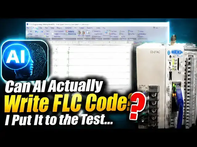

Can AI Actually Write PLC Code? I Put It to the Test...
Aug 24, 2026
Can AI write PLC code? A hands-on test: ChatGPT and Claude were given the same Click PLC motor control task with a normally-closed wiring gotcha. Both wrote working ladder logic — one with Set/Reset, one with a seal-in. Here is the honest verdict.
⚡ QUICK ANSWER
Yes, today's AI can write ladder logic that actually runs. To test it, I gave both ChatGPT and Claude the exact same Click PLC motor control task, with a classic wiring gotcha buried in it: start a motor with the stop and overload wired normally closed (on at rest), plus a two-second warning buzzer before the motor starts. The trap is that a lazy answer uses normally closed contacts in the ladder to match the normally closed buttons, a double negative that would stop the motor from ever starting. Neither AI fell for it. ChatGPT used a Set/Reset latch across seven rungs; Claude used a classic seal-in latch in five rungs. Both handled the wiring correctly, and both produced working programs in two different, valid styles. But there is a catch: they got it right because I gave a clear, specific prompt with the real addresses and the exact sequence. Ask vaguely, and you get generic logic that may not match your wiring. And neither AI thought to hardwire the overload as a backstop, because neither can see your panel. AI can draft correct logic for a task you specify perfectly, but it cannot own the outcome. The full written test and both programs are on the blog below.
📖 FULL WRITTEN TEST + BOTH PROGRAMS + MY RULES FOR AI ON A PLC
https://accautomation.ca/can-ai-actually-write-plc-code-i-put-it-to-the-test/
⏱️ TIMESTAMPS
00:00 Can AI Actually Write PLC Code? I Put It to the Test
00:58 The task I set
01:49 What ChatGPT produced
03:39 What Claude produced
04:29 Both passed — why that matters
04:55 The interesting part: two valid styles
05:37 Why it worked: the prompt
06:12 The one thing I would still add
06:43 I still tested it
07:23 The verdict
🧪 THE TEST
▶ Same Click PLC motor task given to ChatGPT and Claude
▶ Start NO on X1, Stop NC on X2, overload NC on X3, contactor Y1, run light Y2, buzzer Y3
▶ Twist: a 2-second warning buzzer sounds before the motor starts
▶ The gotcha: normally closed wiring on stop and overload (a double-negative trap)
✅ THE RESULTS
▶ ChatGPT: a Set/Reset latch, 7 rungs, each stop condition on its own reset rung
▶ Claude: a classic seal-in latch, 5 rungs, stop and overload in series
▶ Both used normally open contacts for the NC-wired inputs — correct, no double negative
▶ Both working programs; Set/Reset vs seal-in is a real design tradeoff, not right vs wrong
▶ Neither hardwired the overload — that safety judgment is still yours
📚 WHAT YOU'LL LEARN
✅ Whether ChatGPT and Claude can write working Click PLC ladder logic
✅ Why normally closed wiring is a classic trap (the double negative)
✅ The difference between a Set/Reset latch and a seal-in latch
✅ Why a clear, specific prompt is the skill that makes AI useful
✅ Why the overload should be hardwired, and why AI won't tell you that
❓ FREQUENTLY ASKED
Q: Can AI actually write PLC code that works?
A: Yes — both ChatGPT and Claude wrote correct, working ladder logic for a clearly specified Click PLC task, even avoiding a classic normally-closed wiring trap. But that's not the same as programming your machine.
Q: Why did both AIs get the wiring right?
A: Because the prompt was specific — it gave the real addresses and stated that the stop and overload were normally closed and on at rest. A vague prompt gets generic logic that may fall for the double negative.
Q: So can I trust AI to program my PLC?
A: Use it as a drafting tool: write a clear prompt, verify every line, test with outputs isolated, keep safety in hardware, and put your name on it only when you understand it.
👉 Full written test + both programs: https://accautomation.ca/can-ai-actually-write-plc-code-i-put-it-to-the-test/
🔗 MORE RESOURCES
🎮 Prove the logic free — the ACC PLC Simulator Motor Starter scene: https://accautomation.ca/simulator/acc-motor-starter-scene.html
🕹️ Watch the Motor Starter scene: https://youtube.com/shorts/5qVbD0NfhIE
▶ Click PLC Series: https://accautomation.ca/series/click-plc/
▶ PLC Beginners Guide: https://accautomation.ca/programming/plc-beginners-guide/
▶ Free eBooks: https://accautomation.ca (subscribe for download)
🛒 RECOMMENDED HARDWARE
▶ Shop: https://www.automationdirect.com/
▶ Parts Guide: https://www.accautomation.ca/purchase-find-parts/
💬 Set/Reset or seal-in — which would you have written? Drop a comment below.
🔔 New tutorials every Monday — Subscribe and hit the bell!
#PLC #LadderLogic #IndustrialAutomation #PLCProgramming #ACCAutomation #ClickPLC #AIforPLC #MotorControl #ChatGPT #Shorts
Regards,
Garry
ACC Automation
http://www.accautomation.ca
Show More Show Less