Up next in 10

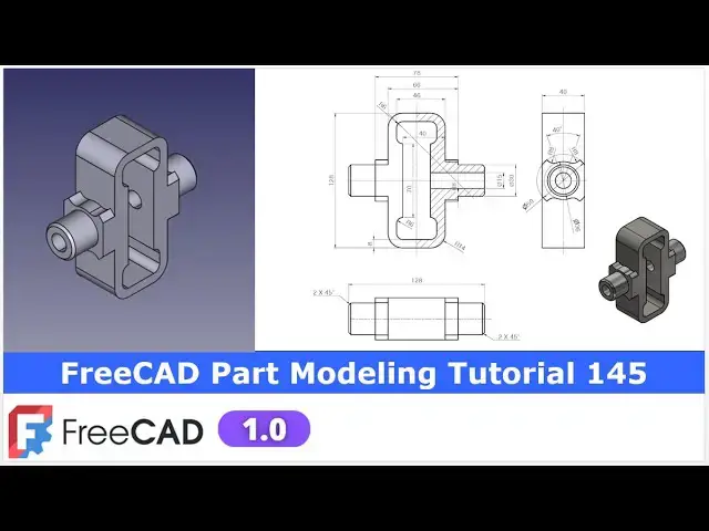
FreeCAD Part Modeling Tutorial 145 | FreeCAD Tutorial | 3D Modeling | Learn FreeCAD | Mechnexus |
Apr 28, 2025
#freecad #freecadtutorial #learnFreeAD
In this video I have explained How to Model Part in FreeCAD with the help of part design Workbench.
▶️ Get my Complete FreeCAD Course : From Zero to Expert !
https://ko-fi.com/s/1ab4385434
▶️ Join my channel membership and keep supporting my work:
https://www.youtube.com/channel/UCcn6z2whMaFu-_LDsEXCfVA/join
▶️ Visit my website for more info on FreeCAD-:
https://mechnexus.com/
▶️ Download Source File of Tutorial-:
https://mechnexus.com/mechnexus-youtube-tutorial-source-file/
▶️ Buy Me a Coffee
I am very grateful that you watch my videos and I am constantly trying to improve the quality of the videos on this channel. If you'd like to help me do this, please consider supporting me so that I can to continue to produce content for your enjoyment.
👉 Help support this channel by buying me a coffee: https://ko-fi.com/mechnexus
Show More Show Less View Video Transcript
0:00
hello friends welcome to free tutorial and in this tutorial we will model this part and uh you can see that uh I have
0:08
already modeled it and uh it is matching with the isometric view of our uh
0:13
reference drawing I will show you how to model this part and uh I will show you how to
0:22
read the dimension of this orthographic and we will create this part This
0:28
tutorial is uh very simple and uh this is designed for the beginner user of a
0:33
free CAD Now I will uh close this file and create a new file and I will uh show
0:41
you from the scratch If you want to learn free CAD from the scratch then you can buy my
0:48
complete free course from zero to expert This course also available on Udemy but
0:55
uh problem is that uh UDMI only give me the 37% of a course selling You can see here
1:03
user had paid $15 but I have only got $5
1:10
So after minus of taxes I get the pennies on each course
1:17
selling If you wanted to see the review of my course you can go to the Udemy and
1:23
s search for the free CAD and you will see my course complete free CAD course
1:29
from zero to expert and this course is took by the more than 2,000 students and
1:36
I have got the rating of a 4.1 for the demo lectures You can expand it
1:43
and uh see the demo lectures and the course structure But I will request you
1:50
if you found my course interesting and uh reviews of the other student on Udemy
1:58
then I would request you to buy my course from the my coffee shops because
2:07
if you buy from here it will help me a lot So once you buy my course you will
2:14
be redirected to the Google drive and here is the my course complete free
2:20
course from zero to expert Go inside and uh the sections I have shown you on my
2:29
Kofi shop page So exactly same lectures
2:34
under the section is created For example section one is a introductions to free
2:41
1.0 and what is new in a freecad 1.0 So if you go to the section one so there
2:48
are the 18 lectures and if you go inside of the sections one you will find the 18
2:56
lecture total And once you go to the lecture one you will find a video file
3:02
which you can download to your system and you can watch it And this course is
3:09
uh updated on a equal interval of a time once the new feature is came And uh once
3:15
you purchase the course you have the lifetime access to the course and in the
3:22
case of any doubt any query you can mail me at admin
3:28
rate.com At the end you will find one uh video which is a promotional video You
3:35
can watch the video and uh take the whole overview of the course You can
3:40
also explore my shop where you can uh download the tutorial source file and
3:46
some interesting projects on free CAD You can find my course link on my
3:53
YouTube channel You can see the course link and uh you can also find my Kofi
4:00
course page link on uh pin comments and uh video descriptions So buy my course
4:08
and uh keep supporting my free CAD works Your small course purchase will uh help
4:15
me to grow this channel and it will also motivate me to create more awesome
4:21
content on free cat So please check out my course on uh free
4:28
CAD from uh 02 expert and now we will come back to our
4:36
tutorial So here I have created a new file and uh now I will insert my
4:42
body and uh I will create a sketch And now as per the part
4:49
orientation we will uh select this YZ plane to create our base profile So
4:59
select the plane and now we will uh read the
5:04
dimensions So here I will select a rectangle tool and I will create a
5:10
rectangle And now we will make it symmetric So here I will use the
5:16
symmetricity constraint and uh make it symmetric And now let's give the
5:25
dimensions Select this horizontal dimension Provide 54 and uh select this
5:31
vertical dimension and provide 128 So our uh sketch is fully
5:38
constrained And now I will close it And now we will uh create the pad of
5:47
40 mm If you see in a side view here we can see So we will uh select the sketch
5:54
Click on the pad and here we will click on symmetric to the plane and uh provide
6:01
the 40 mm Now we will create our next feature
6:09
So if you see the isometric view So here we have a circular profile and here is a
6:17
one more pad feature which is a similar on the other side So we will create it on the left hand side and we will use
6:23
the mid plane to mirror on the other side So let's select this face and click on the sketch And here our model is
6:31
rotated So we will rotate to the right orientation And now let's uh click on the circle
6:39
tool and create a circle Select a diameter option and provide it a 30
6:47
mm And now close it and select the sketch Click on the pad and uh provide
6:55
the value of uh 37 mm
7:00
You can find out this distance with a reference dimension shown in a front and
7:06
top view Now let's uh
7:14
create this profile and for this we will uh select the face and uh click on the
7:24
sketch Now let's uh rotate our model And now here we will switch to the
7:31
wireframe view And let's uh start creating our sketch So first thing we will do is to
7:39
select a circle tool and we will create a circle And if you see our drawing So
7:46
this is the diameter 50 So we will create a circle and uh constrain it with
7:52
the diameter 50 and uh select it and uh make
7:58
it construction And now we will uh create a threepoint arc
8:06
on the both the sides So let's uh select a threepoint arc tool
8:14
And here let's create a threepoint arc and uh select it this and this and add a
8:22
coincidence constraint And now here we will
8:27
uh constrain this point So for this we
8:32
will uh select a line tool and uh create a line and uh we will make
8:41
it coincidence relation with our construction diameter and uh make it a
8:48
coincidence So here select a coincidence select the diameter and this point
8:55
Similarly create one more line and uh add it coincidence or we can
9:02
use the trim tool as well And now select this and this and add a
9:10
coincidence Select this and this and add a coincidence Now here angle is given is
9:18
of 40° So this will be our uh construction line
9:24
and we will select the smart dimension Select this and this and here we will
9:29
provide the 20° Let's give the first dimension on
9:36
the left hand side and give it a 20
9:44
And now we will uh make this
9:49
angle dependent on this So here we will give the name as it is a angle dimension
9:57
So we will represent a for angle and give the 20 So angle 20° say okay And
10:05
now we will uh select a smart dimension and give the
10:11
angle as if I change this angle that should be changed So we will link it So
10:17
here you will see the option of equation and here type
10:25
constraint Once you select this fread will automatically show you So here I
10:31
wanted to link with the A20 which is the angular 20 dimension Select it So once
10:37
it is successful you will see the result 20° and say okay Now you can see that uh this is a
10:46
dependent dimension on this So if I change this angle to 30 then this will
10:52
be changed So this is how you can link the dimension And if I again make it uh
10:58
20 it will be get 20 Now constraint this arc So for
11:05
this we will uh provide the radial dimension as it is a diameter 36 which
11:13
is shown here So we will uh select a smart dimension and uh provide
11:21
it 36 So here R36 is a diameter So here
11:27
we will make it uh 18 mm So you can see that uh we have
11:33
defined the radius we have defined these two points so that our this first arc is got fully constrained Now we will create
11:41
this two arc of R8 So we will uh select a threepoint arc and uh create a arc and
11:51
provide here tangency relation tangent and we will create one
11:57
more arc here Select a three point and uh select this and
12:05
this and uh say the tangent and
12:11
now r8 is given So we will select uh dimension and uh provide it R8 Now here
12:19
we can do the two things We can link the dimensions like this or we can select
12:26
both and uh made it equal So once I change this value this
12:32
and this having the equal relation So if I modify this radius this will be changed So you can see that all three
12:39
arc are the constraint And now we will create a similar profile on the other
12:46
side And now here you might think that we can why we cannot use the mirror So
12:54
if I select this and uh this and use the mirror tool it will be get mirror But
13:01
problem with this mirror that uh it does
13:06
not make a relations like the relations the coincident tangent is given here If
13:12
I mirror it Yeah But uh if I try to move it so you can see that center is not a
13:19
coincidence So we need to coincidences if we are using the mirror tool So as of
13:25
now this is a problem with the frecad mirror tool until and unless we have to
13:32
wait that uh apart from the mirroring the profile free also apply the
13:38
constraint here So because of this issue we will uh create our profile from the
13:44
scratch like we have created on this side So let's uh select a threepoint arc
13:50
and we will uh create a arc and here I will uh make it uh coincidence
13:59
And now we will move it and we will similar
14:05
create a two line of uh 20° on the
14:10
bottom side So select a line tool and uh create a
14:16
line and now select the both and uh make it a
14:23
construction And here we will use the trim tool Let's trim the extra geometry And now
14:32
select this and this and add a coincidence Select this and this and add
14:38
a coincidence Now here we will uh provide the
14:47
dimensions and here we will link the dimensions Go to the equation option and
14:53
type the constraints and here we will see the A20 Say
14:58
okay So we will do the same thing here and we will add a dimension of uh same and here
15:06
we will go to the equations and
15:12
now type constraint and here is a
15:18
20 say okay So now we have the three dependent dimension on this 20 If I make
15:26
it a 25 so everything will be 25 So try
15:32
to link the dimension as much as possible If if a profile is like a
15:40
mirror So here is a mirror profile So now instead of giving a dimensions to
15:48
this radius I will uh simply select the both and uh made it
15:55
equal So you can see the constraint And now we will create these two
16:02
radius So select a threepoint arc Select this and this And uh same on the other
16:11
side And now provide the
16:18
tangency Select this and this and provide the tangency And here we will use the same method Instead of providing
16:25
dimension we will use the equal So try to avoid the dimensions and try
16:34
to add the relation as much as possible like equal symmetricity
16:40
paralty And now here we have created the profile and now we will
16:48
uh project this age which we are seeing So let's uh go to the project geometry
16:55
and project these two edges And now here I will uh draw two vertical line on the both the
17:04
side And now here I will select this and this and add a
17:11
coincidence And uh select this and uh this and add a
17:17
coincidence And now let's select this point and this point add a coincidence
17:23
You can also use the trim option Now I will make it
17:29
coincidence Similarly here make it a coincidence and uh make it a
17:36
coincidence This is also constraint Now we will uh select a threepoint arc and
17:44
uh create arc here And here I will place my arc very close to this construction
17:52
diameter And uh here I will use the tangency You can also use the equal
17:57
constraint Now again I will select a threepoint arc Select this and this and
18:05
place it and uh make it a tangent Now same on the bottom side we will
18:13
do select the threepoint arc and
18:18
uh provide the tangency Similarly on the this
18:24
side select it and uh here let's make it a tangent
18:36
Select this and this and uh add a tangent So you can see that uh our
18:44
sketch is fully constrained And now we will close it And let's switch to the flat
18:55
lines And now create a pad and provide the value 12
19:03
mm Say okay Now we will mirror this uh pad one and pad 002 So here order of
19:11
selection is very important while mirroring So press control key and press
19:16
the first feature pad one and then press the control key and click on the pad 002
19:24
and now click on the mirror Now here logic is that uh order of selection is
19:30
important So it will be get added in a same way And now here we will click on
19:36
the select reference And here we wanted to define our reference along the exit
19:41
plane So you can see that our feature is mirror on the other
19:51
sides Now we will uh provide the fillet as a isometric view We can see that
19:57
there are the four fillet at four corners whose detail we can find here in
20:02
a front view So we can see that there is a fillet of R14 So we will click on the fillet tool
20:11
and here we will select the edges and we will add the ages
20:19
So best part with the fillet is that uh once we select the age it is get
20:25
added here and we can uh remove if any age we have are wrongly
20:32
selected So here now provide the value 14 mm and say okay So our fillet is created
20:43
and now we will create this cut profile So for this we will uh simply select
20:50
this uh face and uh click on the sketch And here we will uh switch to the
20:57
wireframe view for better sketching And now here I will use the polyline tool to
21:05
create a rough profile
21:16
Let's create a rough profile and then we will provide the relevant
21:34
constraint and now we will provide the relevant constraint So starting from the one end
21:41
so this line is not vertical I will select it and make it vertical So here
21:47
it is horizontal It is vertical This is horizontal vertical So we have attached all the
21:56
relations And now let's define the positions of this line And for this we
22:01
will click on the project geometry and project this age Select a smart dimension Select this point and this
22:09
point and provide the dimension 8 mm which we can see here And
22:19
now this to this is of a 70 So we will select the line tool and uh provide it
22:28
70 mm and here we will make this 70 mm
22:33
dimension symmetric to the axis So we will click on the symmetricity
22:40
constraint Click on constraint symmetric Select this point this point and the
22:45
axis So now this has got a constraint And now we will uh click on the project
22:54
geometry options So let's click on the project
22:59
geometry and also project this age
23:05
So now here we will select the smart dimension and uh provide the dimension
23:12
of 38 And uh here we will use the symmetricity constraint Select this and
23:18
this and set axis And now we will uh select this and this and
23:25
uh made it equal and uh set it horizontal So here
23:31
sometimes it took the wrong constraint So we will specific select it and
23:36
provide the horizontal And now let's select this point and this
23:42
point and provide the horizontal constraint And now let's define this point to the 40 mm
23:51
from the edge Select this and this and
23:57
provide 40 mm And now let's see what is the
24:05
unconstrained So we can see that this is the
24:11
unconstrained and this line is constraint So we will select this and this and uh made it equal So here we are
24:19
seeing the conflict So we will uh make it uh control Z And now we have a four
24:27
degree of freedom which we can see that and we will make it
24:32
zero So here bottom position is of 8 mm Same way we will uh define from the top
24:40
to this point is of 8 mm And now let's see what is
24:47
unconstrained So here if you see this line so it should be also symmetric with the
24:56
axis So let's click on the symmetricity constraint Select this point this point
25:04
and the axis And now select this line and this line and made it equal And now
25:11
select this point this line and this line and made it equal So our
25:17
uh sketch is fully constrained
25:22
Now we will create a cut So let's switch to the flat lines view It is not working
25:29
So first switch to the shaded and then switch to the flat lines So here is our
25:35
sketch We can also validate our sketch So we can select it and click on the
25:40
validate options Click on highlight troubleshoot work sets So nothing is highlighting after
25:48
clicking on uh highlight troublesome vertexes So our sketch is
25:54
fine It is a common practice you must follow for the every sketch Select the sketch and uh click on
26:02
the cut And here we can say through all or we can define end condition up to face
26:11
Say okay Now let's uh move to the next
26:16
feature Next feature is to provide the fillet If you see here in a front view
26:23
the R six fillet is given which means that all four fillet at the bottom and all four fillet at the top are having
26:30
the same R six But the problem is that if you provide the exact 6 mm fread
26:36
fillet will fail So press zero and click on the fillet and uh let's first select
26:43
the edges
26:49
Now select this edge on both the side If you are facing a problem in a selection
26:55
then simply zoom it for easier selections Same way on the bottom
27:01
side Select this edge and this edge So here by mistake
27:08
face is selected So we will simply remove it Do not cancel this We can easily remove it if any unwanted is got
27:16
selected Now select this edge and let's select the bottom two
27:26
edges So everything is selected So instead of 6 mm we will provide
27:35
5.99 So you can see that a fillet is created And now let's move to the next
27:42
feature So if you see the isometric view there is a drill
27:47
hole of 15 mm So we will simply select
27:53
the face and uh click on the sketch option and here let's rotate our
28:01
model and uh click on the circle tool and create a circle Select a smart
28:08
dimensions and provide a 15 mm Click on close Select the sketch Click
28:15
on the cut And from here say it through wall and say
28:25
okay Now let's uh move to the drawing and also place our model to the
28:31
isometric view Now you can see that uh we have
28:37
successfully modeled this part and our fread model is a matching with our
28:43
reference isometric view So we have learned how to model
28:48
this part with the help of a part design workbench and we have learned how to add
28:54
a relations between the dimensions We have learned the mirror We have learned
28:59
the fillets basic tools of a free CAD modeling with the part design workbench
29:05
So this is all about this tutorial Thank you for watching and uh thank you for
29:10
your valuable
29:25
time
29:41
Heat
29:49
Heat
30:06
Heat
30:12
Heat Heat
30:34
Heat
30:52
Heat Heat
#CAD & CAM
#Computer Education