live_tv
Livestream Starting Soon
00
Hours
:
00
Minutes
:
00
Seconds
Up next in 10

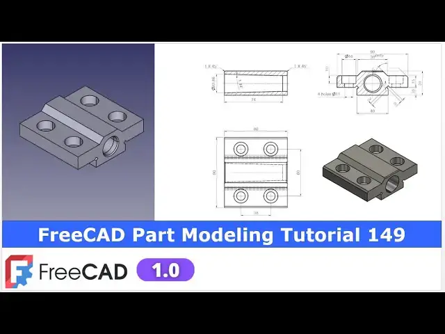
FreeCAD Part Modeling Tutorial 149 | FreeCAD Tutorial | Learn FreeCAD | Mechnexus |
May 3, 2025
#freecad #freecadtutorial #learnFreeAD
In this video I have explained How to Model Part in FreeCAD with the help of part design Workbench.
▶️ Get my Complete FreeCAD Course : From Zero to Expert !
https://ko-fi.com/s/1ab4385434
▶️ Join my channel membership and keep supporting my work:
https://www.youtube.com/channel/UCcn6z2whMaFu-_LDsEXCfVA/join
▶️ Visit my website for more info on FreeCAD-:
https://mechnexus.com/
▶️ Download Source File of Tutorial-:
https://mechnexus.com/mechnexus-youtube-tutorial-source-file/
▶️ Buy Me a Coffee
I am very grateful that you watch my videos and I am constantly trying to improve the quality of the videos on this channel. If you'd like to help me do this, please consider supporting me so that I can to continue to produce content for your enjoyment.
👉 Help support this channel by buying me a coffee: https://ko-fi.com/mechnexus
Show More Show Less View Video Transcript
0:00
hello friends welcome to free tutorial
0:02
and in this tutorial we will model this
0:04
part as you can see that uh I have
0:08
already modeled it and you can see that
0:11
uh it is a perfectly matching with our
0:14
isometric view and if we see the drawing
0:17
so there are lots of thing which we can
0:21
learn from this part like uh how we can
0:24
extrude how we can create a cut and
0:27
especially how we can create counterbore
0:31
holes so this tutorial is uh for the
0:35
beginner user those who have just
0:37
started learning the part modeling and
0:40
uh one more feature which we'll be learn
0:43
here if we see
0:45
the top view and there is a taper
0:49
feature which we will uh learn so now
0:54
let's uh close this file and uh we will
0:58
create this part from the
1:00
scratch and I will show you how you can
1:03
uh create this part from
1:06
uh start to finish so I will uh close
1:09
this file and create a new
1:12
file if you want to learn free CAD from
1:15
the scratch then you can buy my complete
1:18
free course from zero to expert this
1:21
course also available on Udemy but uh
1:25
problem is that uh UDMI only give me the
1:29
37% of a core selling you can see here
1:32
user had paid $15 but I have only got $5
1:40
so after minus of taxes I get the
1:44
pennies on each course
1:46
selling if you wanted to see the review
1:49
of my course you can go to the Udemy and
1:53
s search for the free CAD and you will
1:56
see my course complete free course from
1:59
zero to expert and this course is took
2:02
by the more than 2,000 students and I
2:05
have got the rating of a
2:08
4.1 for the demo lectures you can expand
2:12
it and uh see the demo lectures and the
2:16
course structure but I will request you
2:20
if you found my course interesting and
2:24
uh reviews of the other student on Udemy
2:28
then I would request you to buy my
2:32
course from the my
2:35
coffees because if you buy from here it
2:38
will help me a
2:39
lot so once you buy my course you will
2:43
be redirected to the Google drive and
2:46
here is the my course complete free
2:49
course from zero to expert go inside and
2:54
uh the sections I have shown you on my
2:58
kofi shop page so exactly same lectures
3:03
under the section is created for example
3:08
section one is a introductions to free
3:11
1.0 and what is new in a freecad 1.0 so
3:15
if you go to the section one so there
3:18
are the 18 lectures and if you go inside
3:21
of the sections one you will find the 18
3:25
lecture total and once you go to the
3:28
lecture one you will find a video file
3:31
which you can download to your system
3:34
and you can watch it and this course is
3:39
updated on a equal interval of a time
3:42
once the new feature is came and uh once
3:45
you purchase the course you have the
3:48
lifetime access to the course and in the
3:51
case of any doubt any query you can mail
3:54
me at admin the ratem
3:57
nexus.com at the end you will find one
4:01
uh video which is a promotional video
4:04
you can watch the video and uh take the
4:07
whole overview of the course you can
4:10
also explore my shop where you can uh
4:13
download the tutorial source file and
4:16
some interesting projects on free CAD
4:20
you can find my course link on my
4:23
YouTube channel you can see the course
4:25
link and uh you can also find my Kofi
4:29
course page link on uh pin comments and
4:33
uh video descriptions
4:36
so buy my course and uh keep supporting
4:39
my free CAD works your small course
4:42
purchase will uh help me to grow this
4:45
channel and it will also motivate me to
4:49
create uh more awesome content on free
4:52
CAD
4:53
so please check out my course on free
4:58
CAD from 02 expert and now we will come
5:03
back to our
5:06
tutorial so here I have uh created a new
5:10
file and uh we will use the part design
5:14
workbench to create this part and first
5:17
thing we will insert the body and uh on
5:21
the origin plane and now we will uh
5:24
create our first sketch so for the first
5:28
sketch we will uh refer this uh section
5:31
view and if we see
5:34
the section
5:37
view we can also see the counterboard
5:41
holes
5:42
detail so let's uh start creating our
5:45
profile so we will create this on the
5:48
right face and we will select the right
5:52
plane and uh click on the sketch and now
5:57
let's uh hide the origin
5:59
plane and to create this profile we will
6:04
uh use the polyline
6:06
tool so let's select a
6:10
polyline and uh create an approximate
6:23
profile now if you see that uh free
6:28
automatically applies the constraint
6:30
like vertical horizontal etc now our job
6:35
is
6:36
to provide some additional constraint to
6:41
completely fix our sketch so if you see
6:44
here this is the dimension 19 which is a
6:47
total uh width of our part so we will
6:51
use the symmetricity constraint and
6:54
select this point this point and this
6:57
axis so you can see the two arrows is
7:00
added now we will select a smart
7:02
dimension and uh we will provide it 90
7:08
mm and
7:10
now if we see the height so 10 + 15 is
7:15
of a 25 so I will provide this
7:19
dimension
7:21
25 and now instead of providing the 25
7:25
dimension here we can do two things we
7:29
can select these two points and uh make
7:32
it a
7:33
horizontal or we can select this and
7:36
this and make it equal and
7:41
now let's uh constraint this point so
7:44
select the symmetricity constraint
7:46
select this point this point and this
7:50
axis and uh select a smart dimension and
7:54
provide the
8:00
dimension so if you are facing any
8:03
problem then zoom
8:06
it and uh provide the dimension of uh
8:10
31 and
8:12
uh now let's uh provide the
8:17
angle
8:20
45 select this and this and provide
8:24
it
8:26
45 and
8:28
now provide the overall height which is
8:31
of 31 from the bottom
8:34
point and uh provide this
8:38
31 and now
8:40
here we can uh provide a reference
8:45
dimension select this and uh if you see
8:50
and give the dimension so this is the
8:54
over constraint
8:56
but while giving the dimension we will
8:59
check it as a
9:02
reference so now this is the reference
9:08
dimension and now we will uh close our
9:12
sketch and for this sketch closing you
9:16
can also use this option for exit sketch
9:20
and now let's uh extrude it to the
9:23
distance of 80 mm
9:30
so go to the model tab select the sketch
9:33
and uh click on the extrusion press
9:38
zero give here 80 and from here let's
9:42
switch to the
9:43
isometric and from here keep it
9:46
symmetric to the
9:48
plane and say
9:51
okay
9:53
now if you see our isometric
9:57
view so there is a cut which is same on
10:02
the other side so we will create this
10:04
cut on one side and we will use the mid
10:07
plane to mirror it on the other side so
10:11
for the details we will go to the
10:13
section view and now here I will select
10:17
this face and click on the sketch and I
10:20
will use the project geometry and
10:22
project this uh horizontal and vertical
10:25
edge and uh I will select a twopoint
10:28
rectangle and I will uh create a
10:32
rectangle and
10:33
now I will select a line and create a
10:38
line at a angle and
10:41
then we will uh trim these two edges so
10:46
for this we will use the trim tool click
10:48
on the trim trim this and this and at
10:52
the same time also delete
10:55
this let's uh switch to the wireframe
10:58
view so that you can see sketch more
11:02
clear and now we will uh create this
11:07
profile whose dimension is given here so
11:10
let's select a line
11:12
tool create a two
11:15
line
11:17
and select this and this and add a
11:20
parallel relation and now we will uh
11:23
create a line by joining these two
11:27
points select a line tool select this
11:31
and this and
11:34
here we will apply the relation because
11:38
it is
11:39
flexible so we will select this and this
11:42
and add a
11:45
parallel sorry perpendicular constraint
11:48
so here you can see that
11:49
perpendicularity is added and now let's
11:52
give the dimension select smart
11:55
dimension and uh give it uh 3 mm
12:00
and here we will select this and this
12:04
and uh make it
12:06
equal and now let's also constrain this
12:13
one give the 3 mm or you can delete it
12:18
and apply the relation with this and
12:21
made it
12:22
equal and
12:24
now let's provide the angle
12:28
so select the smart dimension select
12:30
this line and this line and provide the
12:34
angle of
12:36
45 and let's define this
12:40
position which is of 20
12:45
mm and let's define the
12:49
height which is of 10 mm
12:54
so this is how we have constrained our
12:57
sketch with less
13:00
dimensions my advice is to use the
13:03
constraint tools like uh equality
13:08
perpendicularity rather than giving the
13:11
dimension for example instead of uh
13:14
giving perpendicularity I can give the
13:16
angle but to make your sketch more clear
13:21
avoid giving the dimension if you can
13:24
apply the constraint now we will close
13:27
it and uh we will switch to the flat
13:31
lines view select the sketch and uh
13:35
click on the pocket tool and from here
13:38
say it through all and say okay now we
13:42
will select the pocket tool and click on
13:44
the
13:45
mirror and from here we will select
13:49
reference and select this exit plane and
13:51
click on okay so you can see that uh
13:55
this cut is mirror on the other
14:00
side now we will uh create this four
14:03
counterbore holes whose detail we can
14:05
see in a section view it is a diameter
14:08
11 through and counterbore hole is of a
14:12
diameter 18 with a depth of 10 mm so
14:16
here we will select this top face and
14:18
click on the sketch and we will create a
14:21
four
14:22
circle at a
14:25
position given here and uh we will make
14:30
the circle 11 mm so for
14:33
this we will uh create one
14:38
rectangle and we will drag our mouse
14:41
from right to left to select all
14:45
four edges and we will uh toggle it to
14:49
the construction
14:51
geometry now the purpose of creating
14:54
this uh rectangle is to define the
14:57
positions so so once I change this
15:00
rectangle position so then our hole will
15:04
be get shifted because we are making our
15:08
whole center at the corner so let's uh
15:11
select a smart dimension and uh provide
15:15
it
15:17
38 and uh vertical is of uh
15:22
60 this we can see here 38 and 60 so
15:27
provide 60 and
15:32
now let's check the orientation of a
15:35
part whether the orientation is correct
15:37
or not so we can see that
15:41
uh this is of a
15:47
38 and this is of a 60
15:53
so it is very important to check the
15:55
orientation with the isometric view now
15:58
we will switch to the top view and let's
16:03
make it symmetric so here we will first
16:06
switch to the wireframe view so that we
16:09
can see the axis clearly and now uh we
16:12
will use the symmetricity constraint
16:14
select this point this point and this
16:17
axis
16:19
and we will select this point this point
16:23
and this
16:25
axis so you can see that uh our sketch
16:28
is fully constrained and
16:30
now we will uh select a circle
16:34
tool and create a four
16:39
circle and here we will use the smart
16:43
dimension
16:44
and uh here if you see in a section so
16:48
it is a 11 mm drill so we will provide
16:51
here 11 mm and say okay and instead of a
16:57
giving dimensions to all the circles we
16:59
will press control key and select all
17:02
the circles and here we will apply the
17:05
equal constraint so you can see that it
17:08
is created
17:10
now we will create this counter holes so
17:14
let's uh first switch to the flat lines
17:17
view so here you can see that uh if you
17:20
click on here it is not uh activating so
17:23
first switch to the shaded view and then
17:26
click on the flat lines so this is a a
17:29
type of a bug in a free cat and I hope
17:32
so in upcoming release it will be get
17:34
fixed but it is not a major issue select
17:39
the sketch and click on the hole wizard
17:42
so to create a counterboard holes first
17:44
we define our drill size so in a
17:49
practical the operator will drill this
17:52
11
17:53
mm so here we will uh provide 11 mm and
17:57
here simply I will say it through wall
18:00
so operator will first create this 11 mm
18:03
drill and then we will select the
18:05
counter board and here on the
18:07
counterboard diameter is 18 so we will
18:11
provide the 18 and depth is of 10 mm so
18:15
we will provide here the 10 mm and
18:19
now you can see that uh this counter
18:23
board hole is
18:25
created now say
18:28
okay and now let's move to the next
18:31
feature next feature is to create the
18:36
hole which is at a taper of
18:41
1.44 so we will press zero for the
18:45
isometric view and uh we can see that
18:51
uh this uh counterboard
18:54
holes which we have created apart from
18:57
that there is a hole but in the taper so
19:02
if you see the our model orientation and
19:04
if we switch to the wireframe view so
19:08
here we can see that uh taper line is
19:12
here
19:14
so we will select the backside
19:17
face to create our sketch so switch to
19:21
the flat lines press uh zero and let's
19:27
select this back face which is a left
19:30
view
19:31
click on okay and now let's rotate our
19:36
model and uh we will select the circle
19:40
tool and create a circle and here the
19:44
diameter is a given which is of
19:49
23.86 so
19:52
select
19:55
23.86 and say okay and now its position
20:01
we will project geometry and select a
20:04
smart dimension and let's
20:08
define the position of uh 10
20:12
mm and now we will close it and now we
20:16
will create this taper as well with a
20:21
cut because this uh drill size is of a 2
20:27
uh
20:27
23.86 so this type of a drill may not be
20:31
available in a market so it is going to
20:33
be made with a pocket option and
20:37
here if you
20:40
see it is of a 74 mm so first we will
20:44
define our uh cut length of 74 and here
20:49
is a taper angle feature and here in the
20:52
taper angle feature I will provide
20:56
minus
21:00
1.44 which is this
21:03
one now to see that uh we will switch to
21:07
the
21:08
wireframe and say
21:11
okay and
21:14
now let's switch to the top
21:17
view and rotate it so here we can
21:21
clearly see that taper line is created
21:24
as it is a wireframe view therefore
21:29
uh the visualization is little bit poor
21:32
but if you create a drawing by taking a
21:37
sections from the mid you will see it
21:40
and now let's uh press zero for
21:43
isometric and now here is a taper
21:48
and if you see here there is a opening
21:53
on the other side here so here we will
21:57
uh select this
21:58
face and click on the
22:01
sketch now we will rotate our model and
22:04
there is a internal diameter we will uh
22:06
click on it and we will project it
22:12
and we will uh create a
22:20
circle and we will select this and this
22:23
and uh made it
22:26
equal click on close select the sketch
22:31
and uh click on the
22:33
cut and from here say it through
22:39
all now let's press zero for isometric
22:42
view and uh we can uh see the
22:47
cut
22:49
now let's move to the next feature so
22:53
here if we
22:55
see there is a chamfer is given so we
22:59
will provide a chamfer of 1
23:06
mm
23:11
now this completes our model and if you
23:14
see that uh our model is a perfectly
23:17
matching with the isometric view of our
23:20
uh reference drawing if you wanted to
23:22
apply the approximate color then select
23:25
the body and go to the appearances and
23:28
drop down it and in the custom
23:31
appearances select this diffuse color
23:34
and uh
23:36
let's adjust the color and say okay say
23:42
close so you can adjust the color and
23:46
you can see that it is a perfectly
23:48
matching with our isometric
23:51
view so this is all about this tutorial
23:54
and this tutorial is for the beginner
23:56
user so in this tutorial we have learned
24:00
pad pocket mirror whole features and
24:04
also the taper feature how we can
24:06
provide the taper when creating the cut
24:10
so this is all about this tutorial thank
24:13
you for watching and thank you for your
24:15
valuable
24:18
[Music]
24:35
time
24:47
heat
24:52
[Music]
24:56
heat
24:59
[Applause]
25:13
heat heat
25:20
[Music]
25:26
[Applause]
25:28
[Music]
25:30
[Applause]
25:32
[Music]
25:33
[Applause]
25:36
heat
25:37
[Music]
25:42
heat heat heat
25:54
[Music]
#CAD & CAM