live_tv
Livestream Starting Soon
00
Hours
:
00
Minutes
:
00
Seconds
Up next in 10

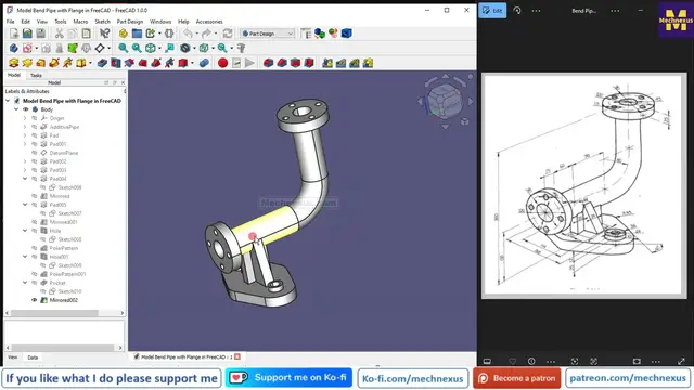
Model Pipe with Flange in FreeCAD : (Gallery Serial No.26) | FreeCAD | Mechnexus |
Oct 29, 2025
#freecad #freecadtutorial #learnFreeAD
In this video I have explained How to Model Part in FreeCAD with the help of part design Workbench.
▶️ Get my Complete FreeCAD Course : From Zero to Expert !
https://ko-fi.com/s/1ab4385434
▶️ Join my channel membership and keep supporting my work:
https://www.youtube.com/channel/UCcn6z2whMaFu-_LDsEXCfVA/join
▶️ Visit my website for more info on FreeCAD-:
https://mechnexus.com/
▶️ Download Source File of Tutorial-:
https://mechnexus.com/mechnexus-youtube-tutorial-source-file/
▶️ Buy Me a Coffee
I am very grateful that you watch my videos and I am constantly trying to improve the quality of the videos on this channel. If you'd like to help me do this, please consider supporting me so that I can to continue to produce content for your enjoyment.
👉 Help support this channel by buying me a coffee: https://ko-fi.com/mechnexus
Show More Show Less View Video Transcript
0:00
hello friends welcome to free CAD tutorial and in this tutorial we will model this pipe with
0:08
flange with respect to the isometric view dimension as you can see that I have already
0:15
model it and I will show you from the scratch how you can model this part this is a very
0:21
interesting model in a free CAD because here we are going to use the swap features we will
0:28
going to design this a base feature and this flanges so this is going to be very
0:35
interesting tutorial in a free CAD part modeling and for this tutorial I am
0:41
using the free CAD version 1.0 so you must have at least 1.0 or higher version
0:48
of a free CAD so I will close this file and we will create this part from the
0:54
scratch let's create a new file and create a body and go to the model tab and
1:02
on the origin now if we read our isometric drawing so this is the
1:07
important area so we will keep our origin here and we will create a outer
1:14
diameter which is of a 64 inner one is of a 45 so select the front plane and
1:21
click on the sketch and let's hide the origin plane select the circle create
1:29
two circle and now provide the inner one is of 45 and outer one is of 64 so here
1:43
we can see that there is a path where this 45 mm diameter material will be get
1:54
removed along the path so we have created the profile and now we will
2:00
create this path so let's come out of the sketch and switch our model to the
2:07
isometric and lets on the origin plane again now we will create a path on the
2:16
right plane which is yz plane and click on the sketch and hide the origin plane
2:22
and here I will select a line tool create one horizontal line and one
2:33
vertical line and now we will use the fillet tool to create a fillet now let's
2:44
constrain it so here we can see that the radius is of our RAT select a smart
2:52
dimension and let's first constrain the radius which of a 80 mm and now we will
3:00
drag this point and extend this line now select a smart dimensions define this is
3:08
of 175 and this one is of 225 now if we subtract the distance here we will get
3:27
it to 25 and our guided path is of fully constrained so let's come out of the
3:36
sketch go to the model tab click on close so this drawing dimension are very
3:44
poor quality but if you zoom it you can see it now we will create the additive
3:57
pipe which is here so first select our first sketch and then second and click
4:09
on the additive pipe so here you can see that it is a perfectly created and keep this selection
4:20
orientation as it is and here you can see that our first sketch is object which means
4:27
that the first sketch we have created is object and the second sketch which is sketch 001
4:36
is our guided curve we will say ok and now we will expand this and hide this sketch so
4:47
this is the base profile because everything is depend on this pipe so we have created
4:56
first features and now let's save our part and I will give this revision R1 because I
5:02
I have already model it and let's create a next features so next features we will
5:09
create this pad which is very easy to create we will simply select the face
5:15
and click on the sketch and we will project this inner diameter and create a
5:24
circle and make this and this equal now I will again select the circle options
5:31
create one more circle and if you zoom it here so we can see that this dimension
5:37
is a 120 we will make it 120 and close it and now create a pad of a 25 mm which
5:50
we can see here select the sketch click on the pad provide it a 25 say ok now the
6:05
similar features is on the top side so we will simply select the top face and
6:10
click on the sketch we will repeat the same operations project the inner
6:17
diameter create a circle and then made it equal again create a circle and provide the
6:31
120 diameter click on close and select the sketch and create a pad which is of a 25
6:47
mm and say okay now our next feature is to create a datum plane now let see the dimension where we have to create a datum plane so if you see here we have a created this 25 mm pad and if we on the origin plane and see
7:12
it from the right directions so here is a dimension 60 is given which is the from this
7:20
here we have to create a datum plane at a 60 distance from the exit plane so I
7:28
have selected this plane and I will simply click on this datum plane and you
7:34
can see that our temporary datum plane is reflecting here if you see from the
7:38
right and now I have to define the direction here so in a z directions
7:44
provide the value 60 but it is moving on the other side simply change the sign
7:53
from plus to minus so once you change the sign it will be get flipped here I
8:00
have a change the sign but it is not reflecting because I have not click on
8:05
the screen so once you click on here you can see that it got reverse and
8:10
attachment mode with a plane face it is successful say ok and now this origin
8:18
plane is not required and we will switch to the isometric view and now we will
8:27
create this triangular profile on this datum plane so here is a one tick mark
8:32
is showing on a datum plane which means that our datum plane needs a rebuilt so
8:38
right click it and click on the recompute object now select the datum plane and click
8:46
on the sketch let's switch our model to the isometric view and here first thing we will
8:54
do is to project this 64 mm diameter click on the project geometry and select this diameter
9:05
so that it will be get projected on the datum plane and now we will switch to the front plane
9:12
and we will also hide this datum plane by pressing the space bar and we will switch to the wireframe
9:19
view and now we will create a three-point arc so select a arc by three point and create an arc
9:31
and simply select the center points and add a coincidence relations and now
9:38
rotate it select this arc and this projected diameter and made it equal now
9:50
select this point and this axis add a coincidence relations similar on the
9:58
other side select this point and axis and add a coincidence relation and now I
10:04
will create one horizontal line and then I will close my profile by joining the
10:15
points now let's make this point and this point symmetric to this axis and
10:28
so click on the symmetricity constraint select this point this point and this
10:35
axis and now here if you see our drawings of 114 dimension is given so
10:42
select a smart dimension and provide the 114 and now let's provide this height
10:50
of 110 so you can see that our sketch is fully constrained and we can see that
11:01
this is the pad of a 24 mm so we will come out of the sketch and let's switch
11:09
our model to the flat lines view select the sketch click on the pad and now here
11:18
we will reverse it and provide that 24 mm so to cross check whether we have a
11:27
did the pad in the right directions we will on our datum plane so it is in the
11:35
right direction because if you see in a drawing so here is a center of diameter
11:43
64 and from this age it is a 24 so our datum plane is here so we have did the
11:50
extrusion in the right direction now off the datum plane press 0 for isometric
11:56
view and we will create our next feature so next feature which will be
12:02
create is the base pad which will be get created on the bottom face of our pad
12:09
which we have created so select the face and click on the sketch and let's see
12:15
our model in a right orientation so here we will project this edges let's click
12:28
on the project geometry and project all the edges and move to the bottom view now
12:37
here we will create one construction line select a line tool and we will make
12:51
it a construction and now we will create two three-point arc on our left hand
13:01
side and one is on the right hand side similarly one will be on top and other
13:06
will be on a bottom so select a three-point arc on both the side and make
13:17
the center horizontal with this construction line point so here specifically I will select the horizontal because sometimes auto one is
13:30
not work similarly on the other side now make it smaller and we will create one more three
13:49
point arc on a top side and one is on the bottom side and here if you see it is not a coincidence relation with axis so we will
14:06
make a coincidence relation on a top as well as on the bottom and now let's
14:14
us constrain this radius so if we see our drawing let's zoom it so this one is of r45 so select a
14:26
smart dimension and provide it a 45 and here I will select this and this made equal relation
14:35
and now it is also a r45 so press ctrl key made it equal similarly this one and
14:47
this one made it equal and now we will complete this profile by connecting the
14:56
point select a line tool select this and this similarly select this and this
15:06
same on the bottom side now all we have to apply the tangency relations select
15:16
this and this and add a tangent select this and this add a tangent similarly on
15:24
on this arc tangent tangent tangent tangent tangent tangent tangent and tangent now if
15:47
you see that our sketch is still not fully constrained so first thing we will
15:55
do is to define the center points if you see here so here we can see the dimension
16:03
165 so we will use the symmetricity constraints select this arc point this
16:09
arc point and this axis so now you can see that symmetricity constraint is
16:19
applied and now we will provide this 165 dimension select a smart dimension
16:23
select this one and this one and provide 165 and from this center to this center
16:36
is of 60.09 select a smart dimension select this arc point and this arc point
16:52
is of 60.09 so here if you see that this angle is a unconstrained and if you see
17:04
our drawing the angle is given the 40 degree so we will select the smart
17:09
dimension select these and this and apply the 40 degree so now you can see
17:16
that with the angle our sketch is fully constrained and now we will come out of
17:22
it press our model to the isometric and now let's see the how much pad we have
17:30
to give so we have to create a pad of 25 mm if we see here so 25 mm is a given so
17:40
select the sketch click on the pad and provide the 25 mm and say ok now we will
17:52
create our next features next feature is to create this pad which is of a height
17:59
of a 12 mm and we can see that this diameter is of 36 so here I will select
18:10
the face click on the sketch switch our model to the isometric so we will create
18:20
this pad with a single pad options so we have a projected this are two radius and
18:26
simply select the circle and create a two circle at the same time and here we
18:34
will switch to the wireframe and now select the both the diameter and apply
18:43
the equal constraints select a smart dimension and give it a 36
18:51
click on close and if you see here this is of a 12 mm pad select the sketch click on the pad and
19:02
provide the 12 mm and now there is a hole of 24 mm so we will select the face and click on the
19:15
sketch click on the project geometry so here you can use the both the option
19:22
either hole or pocket tool so I will create a two circles select this and this
19:35
and made it equal select a smart dimension and provide it a 24 click on
19:45
close select the hole wizard and simply provide the drill size of a 24 and say
19:53
it through all here you can do one more thing you can create a pad and hole on
20:00
one side and then you can mirror it along the y-z plane so both the methods
20:10
are okay but I do not want to use the mirror tool so I have created in a single sketch now let's
20:20
create our next feature next feature is to create this rip of 20 so select the face and click on the
20:32
sketch and here we will rotate our model and click on the project geometry and we will project this
20:39
radius and we will also project this age move to the front and now let's switch
20:50
our model to the wireframe and here we will select a rectangle and create a rectangle and now delete this line select
21:07
this and rotate our model and add a coincidence relation with the projected
21:12
arc select this point and the arc and add a coincidence relation and now this
21:23
is of a 20 mm so first we will make it a symmetric select the symmetricity
21:30
constraint select this and this and this axis tilt our model select a smart
21:40
dimension select the line and provide it a 20 but our sketch is not close so we
21:48
will select a three point arc select this point and this point select this
21:56
and this made it equal so now our sketch is fully constrained we will select the
22:04
sketch click on the pad and the provide the pad of 20 mm and now if you see our
22:14
drawing we can see the pad here which means that this pad is a mirror on the
22:20
other side so here you can create the same sketch and pad on the other side or
22:30
we have to create one datum plane to mirror it on the other side so here is a
22:44
24 mm is given so I will select the face and click on the datum plane and here in
22:52
a Z directions I will provide the 12 mm so it is going on the other side so I
22:58
will change the sign to the minus and say ok and now let's rebuild our datum
23:08
plane select the pad and click on the mirror and here we will select reference
23:17
and we will select the datum plane and you can see that our feature is got
23:27
mirror on the other side say ok now press a space bar and hide this datum plane
23:35
and now let's create the hole so this is the hole of a 15 mm which we can also
23:44
see in a top view so let's switch to the isometric now select the face and click
23:53
on the sketch and now if you see the PCD is given of 90 mm so select the circle
24:02
create one circle and make it a construction select a smart dimension and
24:09
provide it a 90 mm and now if you see that this first hole is on the axis so
24:18
we will create a circle on axis and now make it a coincidence relation and this
24:27
is we can make with a pocket or a hole tool so let's see the diameter so
24:33
diameter is of a 15 is given make it 15 now click on the close and here is of
24:48
thickness is of a 25 mm so we will use the hole wizard tool and our drill size
24:55
is of a 15 and here is our this pad is of a 25 so here dimensions 25 say ok and
25:05
it is a perfectly opening on the other sides now select the hole and we will
25:13
use the polar pattern and here if you see the hole quantity is a 4 so in
25:22
occurrences provide the 4 mm and say ok we will do the same operation on a top
25:30
side select the face and click on the sketch rotate our model and here let's
25:41
project the inner one or outer one let's project the outer one and select a
25:50
circle and this is of diameter 90 select a smart dimension provide the 90 and
26:01
select it and make it construction now select the circle create a circle add a
26:10
coincidence relation with the construction one and then make a a coincidence relation with the axis why I did this because sometimes it does not
26:25
pick up it so I prefer to provide the coincidence constraint but you can
26:30
directly create here now provided a 15 mm click on close and this is the also
26:39
of a 25 mm so we will click on the whole wizard and our drill sizes of
26:48
for 15 mm say ok and now we will use the polar pattern as we have used in a
26:56
previous feature so now here we do not have a axis so here we will go and
27:04
select reference and we will select this outer diameter and in occurrences give
27:13
the 4 mm so here one thing we have a learn we can also select the diameter
27:18
for the polar pattern if we have a not availability of axis here we have a both
27:25
the options either we can select the axis or the diameter say okay we have
27:32
successfully model this pipe with flange from the scratch and this is a very
27:38
interesting model to practice in a free cat and free cat is a capable to make
27:45
this type of a model so this is all about this tutorial how to model pipe
27:52
with a flange in a free cat thank you for watching and thank you for your
27:57
valuable time
#CAD & CAM
#Engineering & Technology