live_tv
Livestream Starting Soon
00
Hours
:
00
Minutes
:
00
Seconds
Up next in 10

FreeCAD Technical Drawing Tutorial | FreeCAD Tutorial | FreeCAD Drawing | Mechnexus |
Sep 22, 2025
#freecad #freecadtutorial #freecaddrawing
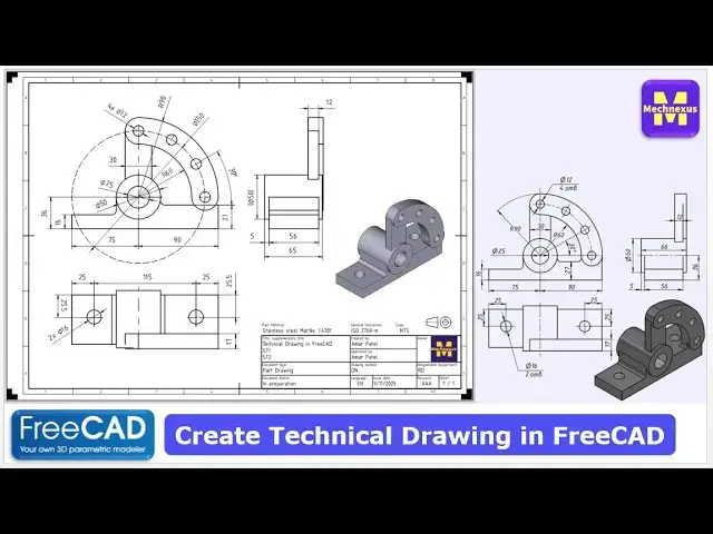
In this video I have explained How to Create Technical Drawing in FreeCAD with Techdraw Workbench
▶️ Get my Complete FreeCAD Course : From Zero to Expert !
https://ko-fi.com/s/1ab4385434
▶️ Join my channel membership and keep supporting my work:
https://www.youtube.com/channel/UCcn6z2whMaFu-_LDsEXCfVA/join
▶️ Visit my website for more info on FreeCAD-:
https://mechnexus.com/
▶️ Download Source File of Tutorial-:
https://mechnexus.com/mechnexus-youtube-tutorial-source-file/
▶️ Buy Me a Coffee
I am very grateful that you watch my videos and I am constantly trying to improve the quality of the videos on this channel. If you'd like to help me do this, please consider supporting me so that I can to continue to produce content for your enjoyment.
👉 Help support this channel by buying me a coffee: https://ko-fi.com/mechnexus
Show More Show Less View Video Transcript
0:01
Hello friends, welcome to fre tutorial
0:03
Hello friends, welcome to fre tutorial
0:03
Hello friends, welcome to fre tutorial and uh in this tutorial we will create a
0:05
and uh in this tutorial we will create a
0:05
and uh in this tutorial we will create a technical drawing in frecad. As you can
0:08
technical drawing in frecad. As you can
0:08
technical drawing in frecad. As you can see that uh I have already modeled this
0:11
see that uh I have already modeled this
0:11
see that uh I have already modeled this part with respect to the reference
0:13
part with respect to the reference
0:13
part with respect to the reference drawing and you can see that our frecad
0:17
drawing and you can see that our frecad
0:17
drawing and you can see that our frecad model is matching with the reference
0:19
model is matching with the reference
0:19
model is matching with the reference drawing isometric view.
0:23
drawing isometric view.
0:23
drawing isometric view. to create a technical drawing in a free
0:25
to create a technical drawing in a free
0:25
to create a technical drawing in a free care we will use the take draw workbench
0:28
care we will use the take draw workbench
0:28
care we will use the take draw workbench but
0:30
but
0:30
but before that uh I am using the freet
0:33
before that uh I am using the freet
0:33
before that uh I am using the freet version 1.0 so you must have at least
0:36
version 1.0 so you must have at least
0:36
version 1.0 so you must have at least 1.0 0 or higher version than this
0:42
1.0 0 or higher version than this
0:42
1.0 0 or higher version than this you can visit my website mcnexus.com
0:45
you can visit my website mcnexus.com
0:45
you can visit my website mcnexus.com where I write articles and uh tutorials
0:48
where I write articles and uh tutorials
0:48
where I write articles and uh tutorials on free and here you can see that I have
0:53
on free and here you can see that I have
0:53
on free and here you can see that I have written so many articles on uh free
0:57
written so many articles on uh free
0:58
written so many articles on uh free you can visit the free tutorials tab
1:02
you can visit the free tutorials tab
1:02
you can visit the free tutorials tab where you will find the stepbystep guide
1:05
where you will find the stepbystep guide
1:05
where you will find the stepbystep guide to model uh part here. I have also
1:09
to model uh part here. I have also
1:09
to model uh part here. I have also written so many free tutorials of a
1:12
written so many free tutorials of a
1:12
written so many free tutorials of a part.
1:13
part.
1:14
part. You can also visit my free 3D models by
1:17
You can also visit my free 3D models by
1:17
You can also visit my free 3D models by clicking on the free 3D models tab. And
1:20
clicking on the free 3D models tab. And
1:20
clicking on the free 3D models tab. And here I have uploaded so many mechanical
1:23
here I have uploaded so many mechanical
1:23
here I have uploaded so many mechanical parts which you can uh download, modify
1:28
parts which you can uh download, modify
1:28
parts which you can uh download, modify and uh use in your projects.
1:33
and uh use in your projects.
1:33
and uh use in your projects. You can also visit my 2D drawing library
1:36
You can also visit my 2D drawing library
1:36
You can also visit my 2D drawing library by clicking on the 2D drawing. Here I
1:39
by clicking on the 2D drawing. Here I
1:39
by clicking on the 2D drawing. Here I have uploaded so many 2D drawings of
1:42
have uploaded so many 2D drawings of
1:42
have uploaded so many 2D drawings of mechanical parts. If you like my method
1:45
mechanical parts. If you like my method
1:45
mechanical parts. If you like my method of teaching then you can support me on
1:48
of teaching then you can support me on
1:48
of teaching then you can support me on coff.com/macus.
1:52
You can buy me a cup of coffee. Your
1:55
You can buy me a cup of coffee. Your
1:55
You can buy me a cup of coffee. Your small support will help this channels to
1:57
small support will help this channels to
1:57
small support will help this channels to grow and uh it will motivate me to
2:00
grow and uh it will motivate me to
2:00
grow and uh it will motivate me to create more awesome content on free CAD.
2:05
create more awesome content on free CAD.
2:05
create more awesome content on free CAD. So let's come back to our tutorial.
2:10
So let's come back to our tutorial.
2:10
So let's come back to our tutorial. Here I have activated the techra
2:12
Here I have activated the techra
2:12
Here I have activated the techra workbench and now I will access my
2:15
workbench and now I will access my
2:15
workbench and now I will access my template library. So you will see here
2:18
template library. So you will see here
2:18
template library. So you will see here the part where your uh templates are
2:21
the part where your uh templates are
2:21
the part where your uh templates are installed and this templates come with a
2:24
installed and this templates come with a
2:24
installed and this templates come with a default installation.
2:26
default installation.
2:26
default installation. So now if we see our drawing so we will
2:29
So now if we see our drawing so we will
2:29
So now if we see our drawing so we will uh prefer A3 template. So here I will
2:34
uh prefer A3 template. So here I will
2:34
uh prefer A3 template. So here I will select the A3 landscape ISO 5457.
2:41
So once I click on the template
2:44
So once I click on the template
2:44
So once I click on the template my template will be get inserted in a
2:47
my template will be get inserted in a
2:47
my template will be get inserted in a new tab
2:49
new tab
2:49
new tab and now
2:51
and now
2:51
and now I will click on the body and click on
2:54
I will click on the body and click on
2:54
I will click on the body and click on the projection group. So once I click on
2:57
the projection group. So once I click on
2:57
the projection group. So once I click on the projection group so you can see that
2:59
the projection group so you can see that
2:59
the projection group so you can see that uh our first view is placed. Now I will
3:03
uh our first view is placed. Now I will
3:03
uh our first view is placed. Now I will uh rotate it.
3:08
We can easily rotate either by left or
3:10
We can easily rotate either by left or
3:10
We can easily rotate either by left or right. So this is the our base view.
3:16
And now
3:19
And now
3:19
And now I will insert the side view.
3:25
Not this I require this one left view.
3:30
Not this I require this one left view.
3:30
Not this I require this one left view. And now I will
3:34
And now I will
3:34
And now I will insert the
3:36
insert the
3:36
insert the So this is the front. This is the top
3:38
So this is the front. This is the top
3:38
So this is the front. This is the top and this is the slide. Now
3:42
and this is the slide. Now
3:42
and this is the slide. Now this is the parent view. So once you
3:43
this is the parent view. So once you
3:43
this is the parent view. So once you move on the parent view then children
3:45
move on the parent view then children
3:45
move on the parent view then children view will automatically get moved.
3:52
And now here our scale is of the paste
3:56
And now here our scale is of the paste
3:56
And now here our scale is of the paste type. We will simply say okay.
4:04
And here
4:06
And here
4:06
And here we will click on the page.
4:11
And here is our scale type is a 1 to 1.
4:16
And here is our scale type is a 1 to 1.
4:16
And here is our scale type is a 1 to 1. So 1 to 1 scale seems to be okay.
4:22
So 1 to 1 scale seems to be okay.
4:22
So 1 to 1 scale seems to be okay. And here is a area for isometric view.
4:27
And here is a area for isometric view.
4:27
And here is a area for isometric view. So we will lock our left hand view. So
4:31
So we will lock our left hand view. So
4:31
So we will lock our left hand view. So let's select the left hand view. Select
4:33
let's select the left hand view. Select
4:33
let's select the left hand view. Select it. lock and top view and set it lock.
4:40
it. lock and top view and set it lock.
4:40
it. lock and top view and set it lock. Now
4:42
Now
4:42
Now we will insert the dimensions. So before
4:45
we will insert the dimensions. So before
4:45
we will insert the dimensions. So before that if you on the frame you will see
4:49
that if you on the frame you will see
4:49
that if you on the frame you will see the small center marks but when you off
4:53
the small center marks but when you off
4:53
the small center marks but when you off it you will not see the center marks. So
4:56
it you will not see the center marks. So
4:56
it you will not see the center marks. So first thing we will do is to insert a
4:58
first thing we will do is to insert a
4:58
first thing we will do is to insert a center marks. So I will press the
5:01
center marks. So I will press the
5:01
center marks. So I will press the control key,
5:09
select this,
5:11
select this,
5:11
select this, this and this and I will insert.
5:17
this and this and I will insert.
5:17
this and this and I will insert. So here add a bolt center lines. Let's
5:20
So here add a bolt center lines. Let's
5:20
So here add a bolt center lines. Let's see it. So you can see that uh a PCD
5:24
see it. So you can see that uh a PCD
5:24
see it. So you can see that uh a PCD center is created. Now here
5:29
center is created. Now here
5:29
center is created. Now here I will on the frame
5:32
I will on the frame
5:32
I will on the frame and in this case I will uh little bit
5:36
and in this case I will uh little bit
5:36
and in this case I will uh little bit make my
5:38
make my
5:38
make my view shorter to the8 scale.
5:45
Now I will off the frame. Now I will uh
5:50
Now I will off the frame. Now I will uh
5:50
Now I will off the frame. Now I will uh select this diameter and uh add a center
5:54
select this diameter and uh add a center
5:54
select this diameter and uh add a center lines
5:56
lines
5:56
lines and here in a top view as well I will
6:00
and here in a top view as well I will
6:00
and here in a top view as well I will select this and this and add a center
6:03
select this and this and add a center
6:03
select this and this and add a center lines.
6:05
lines.
6:05
lines. Now let's uh give the dimensions. So
6:09
Now let's uh give the dimensions. So
6:09
Now let's uh give the dimensions. So here is the first dimension is of R90.
6:13
here is the first dimension is of R90.
6:13
here is the first dimension is of R90. So I will select this radius
6:16
So I will select this radius
6:16
So I will select this radius and give it a R90.
6:19
and give it a R90.
6:19
and give it a R90. And now
6:21
And now
6:21
And now I will give this diameter.
6:25
I will give this diameter.
6:25
I will give this diameter. So here it is of a four quantity. So I
6:28
So here it is of a four quantity. So I
6:28
So here it is of a four quantity. So I will select this 12 mm dimensions
6:31
will select this 12 mm dimensions
6:31
will select this 12 mm dimensions and go here in a format specification
6:34
and go here in a format specification
6:34
and go here in a format specification and here I will give the 4x
6:39
and here I will give the 4x
6:39
and here I will give the 4x which means that die of 12 at four
6:42
which means that die of 12 at four
6:42
which means that die of 12 at four locations
6:43
locations
6:43
locations and now
6:45
and now
6:45
and now I will insert a center line here. So I
6:50
I will insert a center line here. So I
6:50
I will insert a center line here. So I will press control key, select these two
6:52
will press control key, select these two
6:52
will press control key, select these two vertical line. Go here and add a center
6:55
vertical line. Go here and add a center
6:56
vertical line. Go here and add a center line between two lines and say okay.
7:00
line between two lines and say okay.
7:00
line between two lines and say okay. Now I will press control key and again
7:03
Now I will press control key and again
7:03
Now I will press control key and again select these two lines and here I will
7:05
select these two lines and here I will
7:05
select these two lines and here I will select the horizontal dimension.
7:08
select the horizontal dimension.
7:08
select the horizontal dimension. So here
7:11
So here
7:11
So here 30 dimension is inserted.
7:14
30 dimension is inserted.
7:14
30 dimension is inserted. And now I will define this radius R60.
7:22
And
7:25
And
7:25
And this uh outer radius of R90 is already
7:28
this uh outer radius of R90 is already
7:28
this uh outer radius of R90 is already defined.
7:31
defined.
7:31
defined. And now
7:33
And now
7:33
And now here
7:36
here
7:36
here let's define this PCD diameter
7:40
let's define this PCD diameter
7:40
let's define this PCD diameter of 150.
7:43
of 150.
7:43
of 150. So if you see
7:46
So if you see
7:46
So if you see here this is not defined but in our case
7:48
here this is not defined but in our case
7:48
here this is not defined but in our case we will define it. And now let's uh
7:51
we will define it. And now let's uh
7:51
we will define it. And now let's uh define this 27 dimension. So I will
7:54
define this 27 dimension. So I will
7:54
define this 27 dimension. So I will press control key select this two
7:56
press control key select this two
7:56
press control key select this two horizontal line and from here I will
7:59
horizontal line and from here I will
7:59
horizontal line and from here I will select a vertical dimension.
8:03
select a vertical dimension.
8:03
select a vertical dimension. And now from this center line
8:07
And now from this center line
8:07
And now from this center line to
8:09
to
8:09
to this edge I will select the horizontal
8:13
this edge I will select the horizontal
8:13
this edge I will select the horizontal dimension
8:14
dimension
8:14
dimension which is of 90 and from this age to this
8:18
which is of 90 and from this age to this
8:18
which is of 90 and from this age to this center line I will select the horizontal
8:22
center line I will select the horizontal
8:22
center line I will select the horizontal dimension. So here
8:24
dimension. So here
8:24
dimension. So here this center line is not selected. So I
8:28
this center line is not selected. So I
8:28
this center line is not selected. So I will press control key and give the
8:31
will press control key and give the
8:31
will press control key and give the horizontal dimension
8:33
horizontal dimension
8:33
horizontal dimension for 75.
8:36
for 75.
8:36
for 75. Now
8:39
Now
8:39
Now we will define this internal diameter.
8:42
we will define this internal diameter.
8:42
we will define this internal diameter. Select it and
8:45
Select it and
8:45
Select it and give it 25.
8:47
give it 25.
8:47
give it 25. And
8:49
And
8:49
And now we will uh define the angle of uh
8:53
now we will uh define the angle of uh
8:53
now we will uh define the angle of uh this to this
8:59
which is of a 30°.
9:01
which is of a 30°.
9:01
which is of a 30°. And now here we will define this uh
9:05
And now here we will define this uh
9:05
And now here we will define this uh outer diameter
9:08
outer diameter
9:08
outer diameter which is of a 50. Now
9:13
we will save our tri. So you can see
9:17
we will save our tri. So you can see
9:17
we will save our tri. So you can see that uh in a front view
9:20
that uh in a front view
9:20
that uh in a front view we have given all the dimension except
9:23
we have given all the dimension except
9:23
we have given all the dimension except this 16 mm. So let's also give that
9:25
this 16 mm. So let's also give that
9:25
this 16 mm. So let's also give that dimensions.
9:31
And now let's move to the side view. Now
9:35
And now let's move to the side view. Now
9:35
And now let's move to the side view. Now inside view first dimension we will give
9:37
inside view first dimension we will give
9:37
inside view first dimension we will give this uh 12 mm dimension
9:41
this uh 12 mm dimension
9:41
this uh 12 mm dimension and uh overall length of this round
9:44
and uh overall length of this round
9:44
and uh overall length of this round extrusion.
9:48
So here sometimes when you select
9:50
So here sometimes when you select
9:50
So here sometimes when you select directly smart dimension freecat
9:53
directly smart dimension freecat
9:53
directly smart dimension freecat solver
9:55
solver
9:55
solver get confused sometimes. So my advice is
9:58
get confused sometimes. So my advice is
9:58
get confused sometimes. So my advice is that always select the specific
10:00
that always select the specific
10:00
that always select the specific dimensions that I want to give the
10:02
dimensions that I want to give the
10:02
dimensions that I want to give the horizontal dimension.
10:08
So let's wait. So this is of 66 and we
10:13
So let's wait. So this is of 66 and we
10:13
So let's wait. So this is of 66 and we will move it to the oxide. And this 50
10:17
will move it to the oxide. And this 50
10:17
will move it to the oxide. And this 50 mm dimension we have given here. If you
10:21
mm dimension we have given here. If you
10:21
mm dimension we have given here. If you wanted to give in a side view, you can
10:23
wanted to give in a side view, you can
10:23
wanted to give in a side view, you can cue it. No issue. and uh add a prefix
10:27
cue it. No issue. and uh add a prefix
10:27
cue it. No issue. and uh add a prefix diameter.
10:29
diameter.
10:29
diameter. But we will make this dimension as a
10:33
But we will make this dimension as a
10:33
But we will make this dimension as a reference because we have already shown
10:36
reference because we have already shown
10:36
reference because we have already shown this dimension in a front view. Here
10:41
this dimension in a front view. Here
10:41
this dimension in a front view. Here in the drawing the 50 mm diameter is not
10:44
in the drawing the 50 mm diameter is not
10:44
in the drawing the 50 mm diameter is not shown here. So except showing 50 here it
10:48
shown here. So except showing 50 here it
10:48
shown here. So except showing 50 here it is more clear if you show in a front
10:51
is more clear if you show in a front
10:51
is more clear if you show in a front view. So that's what I do.
10:55
view. So that's what I do.
10:55
view. So that's what I do. Now
10:56
Now
10:56
Now let's give the dimensions of this 5 mm.
11:00
let's give the dimensions of this 5 mm.
11:00
let's give the dimensions of this 5 mm. Select this and this and uh give it a
11:05
Select this and this and uh give it a
11:05
Select this and this and uh give it a horizontal dimension of a five. So it is
11:08
horizontal dimension of a five. So it is
11:08
horizontal dimension of a five. So it is a 6 mm.
11:11
a 6 mm.
11:11
a 6 mm. And now
11:14
And now
11:14
And now let's select uh
11:17
let's select uh
11:17
let's select uh so this is a 56
11:20
so this is a 56
11:20
so this is a 56 and five. So this should be the 61.
11:24
and five. So this should be the 61.
11:24
and five. So this should be the 61. So let's go to the model tab
11:28
So let's go to the model tab
11:28
So let's go to the model tab and let's select this phase and this
11:30
and let's select this phase and this
11:30
and let's select this phase and this face. So this is a 66
11:36
and
11:37
and
11:37
and from this to this is of a 6 mm.
11:42
from this to this is of a 6 mm.
11:42
from this to this is of a 6 mm. So let's
11:47
go to the edit pad.
11:50
go to the edit pad.
11:50
go to the edit pad. So it is of uh
11:54
So it is of uh
11:54
So it is of uh 65.
12:02
Let's make it a 65 and say enter.
12:14
Now I will go to the model tab.
12:22
and activate my last features and then I
12:24
and activate my last features and then I
12:24
and activate my last features and then I will go to the drawing.
12:27
will go to the drawing.
12:27
will go to the drawing. So now you can see that uh 6 mm become 5
12:29
So now you can see that uh 6 mm become 5
12:30
So now you can see that uh 6 mm become 5 mm. So free is parametric. If you update
12:33
mm. So free is parametric. If you update
12:33
mm. So free is parametric. If you update your model then your drawing dimension
12:35
your model then your drawing dimension
12:35
your model then your drawing dimension will be get updated automatically.
12:38
will be get updated automatically.
12:38
will be get updated automatically. And now here this uh 36 mm dimension is
12:41
And now here this uh 36 mm dimension is
12:41
And now here this uh 36 mm dimension is shown in a side view but we will show in
12:44
shown in a side view but we will show in
12:44
shown in a side view but we will show in a front view which will give the much
12:47
a front view which will give the much
12:47
a front view which will give the much more clarity. So I will go here and
12:50
more clarity. So I will go here and
12:50
more clarity. So I will go here and select a vertical dimension and this is
12:54
select a vertical dimension and this is
12:54
select a vertical dimension and this is a
13:00
36 dimension. And now
13:03
36 dimension. And now
13:03
36 dimension. And now I will
13:06
I will
13:06
I will move it. Now let's move to the top view.
13:11
move it. Now let's move to the top view.
13:11
move it. Now let's move to the top view. In a top view, we will uh define this
13:16
In a top view, we will uh define this
13:16
In a top view, we will uh define this and this dimension center to center
13:21
and this dimension center to center
13:21
and this dimension center to center which is 115
13:23
which is 115
13:23
which is 115 and
13:26
and
13:26
and define
13:28
define
13:28
define horizontal dimension with the age and
13:31
horizontal dimension with the age and
13:31
horizontal dimension with the age and the center.
13:33
the center.
13:33
the center. So if you are facing in a difficulty in
13:35
So if you are facing in a difficulty in
13:35
So if you are facing in a difficulty in a selection then zoom it.
13:41
So this is 25. So here uh in a drawing
13:46
So this is 25. So here uh in a drawing
13:46
So this is 25. So here uh in a drawing center to center distance is not shown
13:48
center to center distance is not shown
13:48
center to center distance is not shown which is wrong
13:50
which is wrong
13:50
which is wrong because practically we have to define
13:52
because practically we have to define
13:52
because practically we have to define one dimensions and with respect to that
13:55
one dimensions and with respect to that
13:56
one dimensions and with respect to that one dimension you have to define the
13:58
one dimension you have to define the
13:58
one dimension you have to define the others. So here we will select this
14:01
others. So here we will select this
14:01
others. So here we will select this hole. So for this hole we have defined
14:04
hole. So for this hole we have defined
14:04
hole. So for this hole we have defined the horizontal dimension and now I will
14:07
the horizontal dimension and now I will
14:07
the horizontal dimension and now I will define the vertical dimension.
14:13
So here it is a 25.5
14:18
but in actual drawing it is 25.
14:22
but in actual drawing it is 25.
14:22
but in actual drawing it is 25. So
14:24
So
14:24
So let's uh also
14:27
let's uh also
14:27
let's uh also check this dimension. Let's see how much
14:31
check this dimension. Let's see how much
14:31
check this dimension. Let's see how much it is.
14:33
it is.
14:33
it is. So it is a 25. So this is okay but this
14:37
So it is a 25. So this is okay but this
14:37
So it is a 25. So this is okay but this is not okay. So we will go to the model
14:40
is not okay. So we will go to the model
14:40
is not okay. So we will go to the model tab and we will see the where we have
14:44
tab and we will see the where we have
14:44
tab and we will see the where we have created the hole.
14:49
Okay. So this is the hole and we will uh
14:55
Okay. So this is the hole and we will uh
14:55
Okay. So this is the hole and we will uh go to its sketch.
14:59
So here
15:04
here it is showing 25 by 25.
15:10
here it is showing 25 by 25.
15:10
here it is showing 25 by 25. But we have a
15:15
if you see our top view. So our
15:18
if you see our top view. So our
15:18
if you see our top view. So our top view is like this. So here it is
15:21
top view is like this. So here it is
15:22
top view is like this. So here it is showing the 25.
15:26
That seems to be correct.
15:30
So let's close it
15:38
and uh let's see the other one.
15:48
So in other one it is 25 by 25
15:53
So in other one it is 25 by 25
15:53
So in other one it is 25 by 25 and say close.
16:02
Now we will go to the
16:06
drawing and never forget to activate the
16:10
drawing and never forget to activate the
16:10
drawing and never forget to activate the last feature
16:14
and then go to the drawing. So here
16:18
and then go to the drawing. So here
16:18
and then go to the drawing. So here we are seeing is 25.5.
16:28
Let's give this dimension again.
16:34
So it is coming 25.5.
16:39
And let's select let's check this. So it
16:43
And let's select let's check this. So it
16:43
And let's select let's check this. So it is 30.5.
16:46
is 30.5.
16:46
is 30.5. But we have checked the model the pitch
16:48
But we have checked the model the pitch
16:48
But we have checked the model the pitch is of a 25.
16:53
But do not worry we will make this
16:57
But do not worry we will make this
16:57
But do not worry we will make this dimension round off. We will make it
17:00
dimension round off. We will make it
17:00
dimension round off. We will make it zero or we will make it to the one.
17:06
So here
17:11
we have to rectify that why this is 25
17:15
we have to rectify that why this is 25
17:15
we have to rectify that why this is 25 is coming.
17:17
is coming.
17:17
is coming. Let's uh
17:20
Let's uh
17:20
Let's uh let's select this diameter and this
17:23
let's select this diameter and this
17:23
let's select this diameter and this center and let's go in a
17:29
center and let's go in a
17:29
center and let's go in a part design workbench
17:31
part design workbench
17:32
part design workbench and here let's select uh
17:38
so 17 + 8. So 17 + 8 is of a 25. So
17:46
so 17 + 8. So 17 + 8 is of a 25. So
17:46
so 17 + 8. So 17 + 8 is of a 25. So everything seems to be correct.
17:51
So we will forget about it
17:54
So we will forget about it
17:54
So we will forget about it because our model is correct and I am
17:57
because our model is correct and I am
17:57
because our model is correct and I am also not able to figure out it why it is
17:59
also not able to figure out it why it is
17:59
also not able to figure out it why it is coming the 25.5 on the drawing.
18:04
coming the 25.5 on the drawing.
18:04
coming the 25.5 on the drawing. If we select the center
18:09
If we select the center
18:09
If we select the center of the hole with this line and if you
18:12
of the hole with this line and if you
18:12
of the hole with this line and if you measure it again and go here in a
18:15
measure it again and go here in a
18:16
measure it again and go here in a distance. So we can clearly see that it
18:18
distance. So we can clearly see that it
18:18
distance. So we can clearly see that it is a exact 25 and this value is round
18:22
is a exact 25 and this value is round
18:22
is a exact 25 and this value is round off.
18:25
off.
18:25
off. So that might be the bug why it is
18:28
So that might be the bug why it is
18:28
So that might be the bug why it is coming the
18:30
coming the
18:30
coming the 25. If you zoom it, so it is perfectly
18:33
25. If you zoom it, so it is perfectly
18:34
25. If you zoom it, so it is perfectly taking the center lines. And if you zoom
18:37
taking the center lines. And if you zoom
18:37
taking the center lines. And if you zoom it
18:39
it
18:39
it here also
18:44
and we are make measuring this dimension
18:46
and we are make measuring this dimension
18:46
and we are make measuring this dimension in the right directions.
18:48
in the right directions.
18:48
in the right directions. Okay, leave it and uh let's proceed. So
18:52
Okay, leave it and uh let's proceed. So
18:52
Okay, leave it and uh let's proceed. So here we have defined the horizontal and
18:54
here we have defined the horizontal and
18:54
here we have defined the horizontal and vertical and center to center 115 and
18:59
vertical and center to center 115 and
18:59
vertical and center to center 115 and this is and here
19:04
we will also define this uh vertical
19:07
we will also define this uh vertical
19:07
we will also define this uh vertical dimension. So I will select the center
19:09
dimension. So I will select the center
19:09
dimension. So I will select the center lines and this
19:12
lines and this
19:12
lines and this and uh
19:14
and uh
19:14
and uh go with the vertical dimension.
19:19
And now
19:21
And now
19:21
And now we will uh define the diameter.
19:25
we will uh define the diameter.
19:25
we will uh define the diameter. This is a 16 but this is of a two
19:28
This is a 16 but this is of a two
19:28
This is a 16 but this is of a two quantity. Go to the model tab. Select it
19:32
quantity. Go to the model tab. Select it
19:32
quantity. Go to the model tab. Select it and expand it and in a format
19:36
and expand it and in a format
19:36
and expand it and in a format specifications.
19:38
specifications.
19:38
specifications. I will give the 2x.
19:43
So now
19:45
So now
19:45
So now we have given all the dimensions
19:48
we have given all the dimensions
19:48
we have given all the dimensions front, top and side and here this
19:51
front, top and side and here this
19:51
front, top and side and here this thickness has to be defined. So I will
19:55
thickness has to be defined. So I will
19:55
thickness has to be defined. So I will select this two horizontal line and give
19:59
select this two horizontal line and give
19:59
select this two horizontal line and give it a vertical dimension.
20:03
So have patience.
20:05
So have patience.
20:05
So have patience. So 17 mm.
20:09
So 17 mm.
20:09
So 17 mm. Now let's uh insert the isometric view.
20:13
Now let's uh insert the isometric view.
20:13
Now let's uh insert the isometric view. So select the body and click on the
20:15
So select the body and click on the
20:15
So select the body and click on the camera icon and here
20:20
camera icon and here
20:20
camera icon and here check this no background
20:23
check this no background
20:23
check this no background and click on the crop image and say
20:26
and click on the crop image and say
20:26
and click on the crop image and say okay.
20:33
So here the view is inserted but it is
20:36
So here the view is inserted but it is
20:36
So here the view is inserted but it is not the
20:38
not the
20:38
not the active view which we want. So we'll on
20:42
active view which we want. So we'll on
20:42
active view which we want. So we'll on the frame
20:45
the frame
20:45
the frame and we will select it and delete it.
20:49
and we will select it and delete it.
20:50
and we will select it and delete it. Now
20:52
Now
20:52
Now to insert active view first we will
20:55
to insert active view first we will
20:56
to insert active view first we will switch to the isometric and then we will
20:58
switch to the isometric and then we will
20:58
switch to the isometric and then we will switch to the fit all
21:01
switch to the fit all
21:01
switch to the fit all and then we will switch to the tectra
21:04
and then we will switch to the tectra
21:04
and then we will switch to the tectra workbench and then click on this camera
21:08
workbench and then click on this camera
21:08
workbench and then click on this camera icon. Click on the crop image and say
21:10
icon. Click on the crop image and say
21:10
icon. Click on the crop image and say okay. Now move to the page
21:15
okay. Now move to the page
21:15
okay. Now move to the page and here
21:17
and here
21:17
and here you can see that uh view is inserted.
21:20
you can see that uh view is inserted.
21:20
you can see that uh view is inserted. Now we will uh
21:25
make it larger. So let's make it scale
21:28
make it larger. So let's make it scale
21:28
make it larger. So let's make it scale 1.3.
21:31
And here
21:34
And here
21:34
And here width we will make it 100.
21:39
width we will make it 100.
21:39
width we will make it 100. So on 100 it is not cropping my model or
21:43
So on 100 it is not cropping my model or
21:43
So on 100 it is not cropping my model or let's make a 105
21:47
let's make a 105
21:47
let's make a 105 and uh height let's make a 110
21:52
and uh height let's make a 110
21:52
and uh height let's make a 110 let's make it a 115
21:55
let's make it a 115
21:55
let's make it a 115 like make 117
21:58
like make 117
21:58
like make 117 and move it
22:02
and here is some space is left so I will
22:06
and here is some space is left so I will
22:06
and here is some space is left so I will unlock it.
22:10
Click on unlock and move it to the left
22:14
Click on unlock and move it to the left
22:14
Click on unlock and move it to the left hand side and then again lock it. Now
22:19
hand side and then again lock it. Now
22:19
hand side and then again lock it. Now I will move my active view here
22:23
I will move my active view here
22:23
I will move my active view here and uh now we will go to the template
22:27
and uh now we will go to the template
22:27
and uh now we will go to the template area. So here you can specify the
22:29
area. So here you can specify the
22:29
area. So here you can specify the material gel tolerance and here is the
22:32
material gel tolerance and here is the
22:32
material gel tolerance and here is the scale. So scale I will give the NTS
22:35
scale. So scale I will give the NTS
22:35
scale. So scale I will give the NTS because my drawing is not to scale
22:39
because my drawing is not to scale
22:39
because my drawing is not to scale and uh title is a create technical
22:41
and uh title is a create technical
22:42
and uh title is a create technical drawing in freeat. So title is too
22:44
drawing in freeat. So title is too
22:44
drawing in freeat. So title is too lengthy. So I will remove this uh create
22:48
lengthy. So I will remove this uh create
22:48
lengthy. So I will remove this uh create word technical drawing in frecad
22:52
word technical drawing in frecad
22:52
word technical drawing in frecad and instead of a component drawing I
22:55
and instead of a component drawing I
22:55
and instead of a component drawing I will give the part drawing.
22:58
will give the part drawing.
22:58
will give the part drawing. Now preparation in status created by
23:02
Now preparation in status created by
23:02
Now preparation in status created by here I will give my name Amar Patel
23:13
say okay drawing number you can give it
23:15
say okay drawing number you can give it
23:15
say okay drawing number you can give it and here is the language
23:18
and here is the language
23:18
and here is the language date and uh revision and here is the
23:24
date and uh revision and here is the
23:24
date and uh revision and here is the options to insert a logo. To insert a
23:27
options to insert a logo. To insert a
23:27
options to insert a logo. To insert a logo, I will switch to the tectra
23:30
logo, I will switch to the tectra
23:30
logo, I will switch to the tectra and tectra views. And here you will see
23:33
and tectra views. And here you will see
23:33
and tectra views. And here you will see the option of insert bit map image.
23:35
the option of insert bit map image.
23:35
the option of insert bit map image. Click on it and I will uh move to the my
23:40
Click on it and I will uh move to the my
23:40
Click on it and I will uh move to the my existing folder
23:43
existing folder
23:43
existing folder of any
23:47
previous uh
23:49
previous uh
23:50
previous uh my part where I have stored my logo and
23:52
my part where I have stored my logo and
23:52
my part where I have stored my logo and I will uh insert it.
23:57
So my logo insertion in a process. So
24:01
So my logo insertion in a process. So
24:01
So my logo insertion in a process. So you can see that uh it is inserted
24:04
you can see that uh it is inserted
24:04
you can see that uh it is inserted but now my logo is large.
24:08
but now my logo is large.
24:08
but now my logo is large. So I will select it and move it and then
24:14
So I will select it and move it and then
24:14
So I will select it and move it and then I will change the scale to the 0 4
24:20
and uh
24:22
and uh
24:22
and uh move it here.
24:26
Now I will off the frame.
24:30
Now I will off the frame.
24:30
Now I will off the frame. So you can see that uh we have uh
24:33
So you can see that uh we have uh
24:33
So you can see that uh we have uh successfully created a technical drawing
24:37
successfully created a technical drawing
24:37
successfully created a technical drawing in a free CAD with the help of a techra
24:40
in a free CAD with the help of a techra
24:40
in a free CAD with the help of a techra workbench and here we have also
24:43
workbench and here we have also
24:43
workbench and here we have also improvised our uh drawing.
24:47
improvised our uh drawing.
24:47
improvised our uh drawing. So this is all about this tutorial how
24:49
So this is all about this tutorial how
24:49
So this is all about this tutorial how to create a technical drawing in a free
24:53
to create a technical drawing in a free
24:53
to create a technical drawing in a free CAD with the help of a tech draw bench.
24:56
CAD with the help of a tech draw bench.
24:56
CAD with the help of a tech draw bench. Thank you for watching and thank you for
24:58
Thank you for watching and thank you for
24:58
Thank you for watching and thank you for your valuable time.
25:01
your valuable time.
25:01
your valuable time. [Music]
25:27
Heat. Heat.
25:30
Heat. Heat.
25:30
Heat. Heat. [Music]
#CAD & CAM
#Software
#Engineering & Technology