live_tv
Livestream Starting Soon
00
Hours
:
00
Minutes
:
00
Seconds
Up next in 10

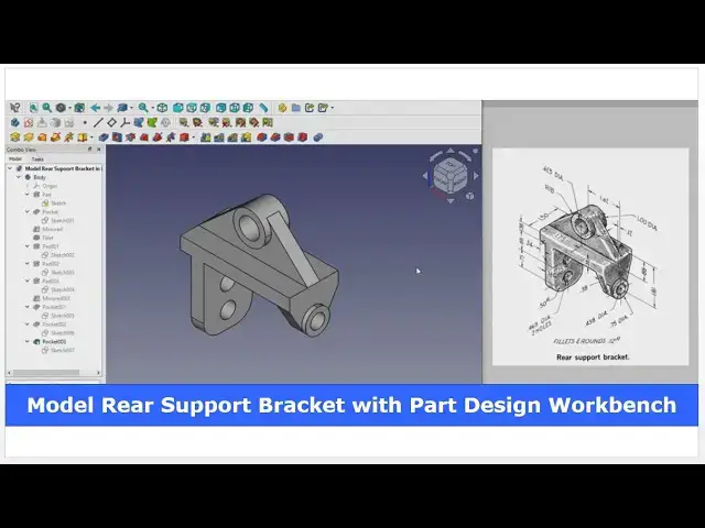
Model Rear Support Bracket with FreeCAD Part Design Workbench | FreeCAD Tutorial | Mechnexus |
May 16, 2025
#freecad #freecadtutorial #learnFreeAD
In this video I have explained How to Model Rear Support Bracket with FreeCAD Part Design Workbench.
▶️ Get my Complete FreeCAD Course : From Zero to Expert !
https://ko-fi.com/s/1ab4385434
▶️ Join my channel membership and keep supporting my work:
https://www.youtube.com/channel/UCcn6z2whMaFu-_LDsEXCfVA/join
▶️ Visit my website for more info on FreeCAD-:
https://mechnexus.com/
▶️ Download Source File of Tutorial-:
https://mechnexus.com/mechnexus-youtube-tutorial-source-file/
▶️ Buy Me a Coffee
I am very grateful that you watch my videos and I am constantly trying to improve the quality of the videos on this channel. If you'd like to help me do this, please consider supporting me so that I can to continue to produce content for your enjoyment.
👉 Help support this channel by buying me a coffee: https://ko-fi.com/mechnexus
Show More Show Less View Video Transcript
0:00
hello friends welcome to Freka tutorial
0:02
and in this tutorial we will model this
0:05
uh rear support bracket As you can see
0:07
that I have already modeled it and I
0:10
will show you from the scratch how you
0:12
can do the same So I will close this
0:15
file and create a new file If you want
0:18
to learn free CAD from the scratch then
0:20
you can buy my complete free course from
0:24
zero to expert This course also
0:26
available on Udemy but uh problem is
0:30
that uh UDMI only give me the
0:33
37% of a course selling You can see here
0:36
user had paid $15 but I have only got $5
0:44
If you wanted to see the review of my
0:46
course you can go to the Udemy and s
0:50
search for the free CAD and you will see
0:53
my course complete free course from zero
0:55
to expert and this course is took by the
0:59
more than 2,000 students and I have got
1:03
the rating of
1:05
4.1 for the demo lectures You can expand
1:08
it and uh see the demo lectures and the
1:13
course structure But I will request you
1:16
if you found my course interesting and
1:20
uh reviews of the other student on Udemy
1:24
then I would request you to buy my
1:28
course from the my coffee shops because
1:33
if you buy from here it will help me a
1:36
lot So once you buy my course you will
1:40
be redirected to the Google drive and
1:42
here is the my course complete free
1:46
course from zero to expert go inside and
1:50
uh the sections I have shown you on my
1:55
kofi shop page So exactly same lectures
2:00
under the section is created For example
2:04
section one is a introductions to free
2:07
1.0 and what is new in a freecad 1.0 So
2:11
if you go to the section one so there
2:14
are the 18 lectures and if you go inside
2:18
of the sections one you will find the 18
2:21
lecture total And once you go to the
2:24
lecture one you will find a video file
2:27
which you can download to your system
2:31
and you can watch it And this course is
2:35
updated on a equal interval of a time
2:38
once the new feature is came And uh once
2:41
you purchase the course you have the
2:44
lifetime access to the course and in the
2:48
case of any doubt any query you can mail
2:51
me at admin
2:54
ratemnexus.com you can find my course
2:56
link on my YouTube channel You can see
3:00
the course link and uh you can also find
3:03
my Kofi course page link on uh pin
3:07
comments and uh video
3:09
descriptions So here I have created a
3:12
new file and I will on my origin planes
3:15
and I will check my units because this
3:18
dimension are in inches So here I have
3:21
selected US customary inch and pound
3:25
Click on apply And now we will select
3:28
this front plane and click on the sketch
3:31
Go to the model tab and hide the
3:35
plane And here first we will create this
3:41
profile So I will use the polyline tool
3:45
to create a approximate profile
3:50
Just draw the profile and then we will
3:53
remove the
4:00
conflict and
4:03
now deactivate it And now we will add
4:07
the horizontal and vertical
4:09
relation This is the vertical and this
4:13
is the
4:14
horizontal and this is also horizontal
4:18
Now give the dimension Select horizontal
4:20
line Select this point and this point
4:23
And add the dimension of 1.75 in From
4:27
this point to this point add a
4:30
horizontal dimension of 1.62
4:34
in Now I will move it to the
4:37
inside This
4:39
also And
4:41
now we will create one horizontal line
4:45
which will represent this center
4:48
axis So we will uh click on line tool
4:52
and create a line And we will make it
4:56
construction and select this point and
4:59
this point Add a vertical dimension of
5:01
uh 888
5:05
in And from this point to this point
5:10
vertical dimension of uh
5:13
2.185
5:18
in And this one will be the
5:26
0.38
5:30
and select uh this point and this
5:34
point and add the dimension of 2.13
5:40
in And select this line and add a
5:44
vertical dimension of
5:48
38 And
5:52
now select this horizontal line and add
5:55
a dimension of uh 34
6:00
in and move the
6:02
dimension Move it Select this point and
6:06
this point and add a horizontal
6:09
dimension and select this and uh this
6:14
and made it
6:16
equal So our uh profile is fully
6:20
constrained We will come out of the
6:23
sketch and we will extrude it to the 1.5
6:26
in Select and give 1.5 in and uh keep it
6:33
symmetric to the
6:36
plane Click on
6:38
okay Now we will uh create the cut
6:42
profile here at this area So we will
6:44
select this phase and click on the
6:46
sketch
6:47
And we will switch to the
6:49
isometric Click on project geometry and
6:52
project this horizontal and vertical And
6:56
uh we will select a threepoint arc
6:59
Create a threepoint arc And select this
7:03
and this And uh add a
7:07
tangent Select this and this axis and
7:10
add a coincidence And here we will
7:13
select diameter and add a diameter
7:16
of 75
7:18
in And we will select a line
7:22
tool Create a line
7:25
and close the
7:28
profile And then we will uh select the
7:32
conflict and uh deactivate
7:38
it Deactivate And here we will add a
7:43
tangency And from this point to this
7:49
point vertical
7:51
dimension is of
7:54
uh
7:56
38 So this is our fully constrained
7:59
profile and we will close it Select the
8:02
sketch and click on extrude cut Select
8:06
uh up to face and select this inside
8:09
face and click on
8:12
okay Now switch to the
8:14
isometric Now here we will on our origin
8:18
plane and uh we will select the pocket
8:20
and click on the mirror And here we will
8:23
select the reference and we will select
8:25
this mid plane and click on okay Now we
8:29
will off the origin plane So we can see
8:31
that uh our cut has been mirror on the
8:34
other
8:35
side Now let's uh move to the next
8:39
feature which is create this boss So we
8:43
will select the face and uh create a
8:47
sketch Switch to the isometric
8:50
Click on project geometry and project
8:52
this and switch to the right plane and
8:55
select circle and uh create a circle
9:00
Click on close Say extrude and extrude
9:04
it to the.12
9:07
in.12 in Click on okay
9:13
Now we will create this
9:17
uh rib or we can say plate type feature
9:22
So this comes on our mid plane So we
9:25
will select the mid plane and click on
9:27
the sketch and uh we will hide our
9:30
origin plane and from here we will
9:33
switch to the wireframe We will click on
9:36
the project geometry and project this
9:38
edge Now select the line tool and
9:44
uh create a line And now we will select
9:48
a
9:49
line and
9:53
uh join this And from here click on the
9:56
fillet and uh give the fillet of uh 0.5
10:01
So select the radius and uh give it uh
10:05
0.5 in
10:08
and uh select this point and this point
10:11
and add a vertical dimension of88
10:15
in And here we will select this and this
10:19
and uh add a vertical
10:23
relation Our uh sketch is fully
10:25
constrained We will come out of it Press
10:28
V7 for shaded view And we will uh select
10:33
the sketch Click on extrude And here
10:35
thickness is of 38 in And uh we will
10:40
keep it symmetric to the
10:44
plane Now we will create this boss So we
10:48
will select the face and click on the
10:50
sketch Click on the project
10:53
geometry Select the
10:56
circle Create a
10:59
circle And uh we will add the material
11:03
of.18
11:07
in Now click on okay So here this and
11:11
this seems to be a separate solid So we
11:14
will refine the
11:16
shape Refine set it true And now we will
11:21
mirror this pad on the other side So we
11:23
will click on the mirror and from here
11:26
select reference and select this mid
11:29
plane and we will also refine this
11:32
mirror So click on mirror refine set it
11:37
true Now we will move to the next
11:40
feature which is to create a hole So we
11:44
will select the face and uh click on the
11:49
sketch rotate it
11:52
Click on uh project geometry and here we
11:55
will uh create a circle of uh
12:00
438 So select diameter and provide
12:05
438 Click on close Select text cut
12:11
Select uh to face and select the back
12:15
face Click on
12:17
okay Switch to the isometric
12:21
Now we will move to the next
12:24
feature which is to add this fillet and
12:29
then we will add this hole So here is a
12:32
fillet is a 0.5 R So we will select this
12:36
edge by pressing the control key and we
12:40
will select this edge and click on the
12:43
fillet and here we will give the
12:48
0.5 in
12:51
symbol Click on okay Now press zero for
12:54
isometric and uh we will uh create this
12:59
two holes on this face So we have
13:02
selected the phase and we will click on
13:04
the sketch and we will switch to the
13:07
isometric switch to the right plane and
13:10
here we will switch to the wireframe and
13:14
uh we will create a two circle on this
13:16
axis Select the
13:21
circle and
13:23
now we will select this and this and uh
13:27
add it
13:28
equal Select one of the circle and add a
13:33
diameter of
13:34
uh
13:41
465 And
13:43
now we will rotate our model Switch to
13:47
the shaded
13:55
view And here we will project this
14:00
edge And now we will switch to the right
14:02
view and switch to the
14:05
wireframe Select this and this and add a
14:09
vertical
14:14
dimension 888 and from this center to
14:20
this center is
14:21
of 75
14:27
Click on close Press V7 for shaded And
14:32
uh select the sketch Click on extrude
14:34
cut And here we will say it true all Say
14:39
okay Now we will uh create a hole here
14:43
So we will press uh zero for isometric
14:46
view and select the face Click on the
14:49
sketch Click on project geometry and
14:51
project it
14:53
and uh create a circle and uh this is of
14:58
a
15:00
diameter
15:03
625 Click on close and say extrude cut
15:07
and from here say true all Say
15:13
okay So this is how we have converted
15:17
this uh rear support bracket into the 3D
15:19
model Here is a common fillet of a point
15:22
R2R which you can provide to the
15:25
model So this is all about this tutorial
15:29
how to make a rear support bracket in a
15:33
free care and in this tutorial all
15:36
dimensions where in inches So we have
15:39
also learned how to set the unit and
15:41
model a part in a inch dimensions So
15:45
this is all about this tutorial Thank
15:47
you for watching and thank you for your
15:49
valuable time
15:51
[Music]
16:21
Heat
16:25
[Music]
16:29
Heat Heat Heat
16:32
[Applause]
16:35
[Music]
#CAD & CAM
#Engineering & Technology