0:01
Hello friends welcome to Solid Works
0:02
tutorial and in this tutorial we will
0:04
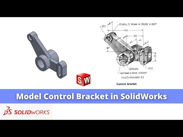
model this uh control bracket in solid
0:09
works as you can see that I have already
0:11
modeled it and I will show you from the
0:13
scratch how you can do the same in Solid
0:16
box so I will close this file and create
0:21
file you can also visit my website macn
0:25
nexus.com and you can visit this solid
0:28
works tutorial tab where I have written
0:32
so many tutorials on uh solid works
0:35
where you can follow the step by step
0:41
parts if you like my method of teaching
0:43
then you can also support me on kofi.com
0:46
you can buy me a cup of coffee your
0:50
small support will help these channels
0:52
to grow and it will motivate me to
0:55
create more awesome content on solid
0:58
works so let's come back to our
1:01
tutorial so here I have created a new
1:04
file and now first we will create this
1:08
uh cylindrical or circular portion
1:12
because this is our the main features
1:15
and base on this main feature we will
1:17
draw the rest of the feature so for this
1:20
we will select the front
1:22
plane and uh create a two
1:28
Circle inner one diameter is of
1:35
25 and outer diameter is of
1:43
T and uh we will come out of the
1:50
now we will select the sketch click on
1:53
uh extrude and we will create Extrusion
1:58
mm and we will keep it uh symmetric to
2:05
plane and now we will select the ph and
2:09
uh click on the plane and we will create
2:12
a datm plane at a distance of
2:15
15 and from here we will click on flip
2:22
okay and now we will uh select our newly
2:26
created plane and click on the sketch
2:30
and switch to the front
2:35
plane and first we will select this
2:39
outer diameter and click on convert
2:42
entities and make it for the
2:48
construction and we will draw a
2:54
line and make it construction and select
3:02
uh create a line and also make it a
3:07
construction and we will create here a
3:12
circle which is of a diameter
3:22
22 and we will also make it a
3:26
construction and from Center
3:30
to this Center is of 50
3:50
45° and we will extend this
3:53
line and just for convenience we will
3:58
create one more line and make it
4:05
now we will select a three-point
4:14
Arc create a three-point Arc equal to
4:18
this and also create a three-point
4:21
Arc equal to the construction
4:24
Circle and now we will select the line
4:27
tool and create a line line by joining
4:30
these two points similarly select a line
4:35
and create a line with joining these two
4:38
points now here we will select this line
4:42
and this Arc and uh make it uh
4:46
tangent similarly select this line and
4:52
tangent similarly here make it a
4:57
tangent select this and this and uh make
5:07
tangent so here our profile is fully
5:10
constrained we will come out of
5:13
it select the sketch click on
5:18
extrude click on flip and here Extrusion
5:31
now we will create a plane made of this
5:34
two face so we will reference go to the
5:38
plane and select these two
5:48
now we will hide this plane now we will
5:51
select this phase and uh click on the
5:54
sketch and make this phase
5:57
normal click on the circle and create a
6:02
this so we will create a larger Circle
6:06
and then select this age and circle and
6:11
equal we will come out of it and
6:19
extrude and give the 3
6:25
okay now we will mirror this extrude
6:41
now here is a counter board hole so we
6:45
will select the face and click on the
6:51
wizard now we will switch to the front
6:54
view and here we will select the counter
6:57
board and here we will go with the
6:59
custom sizing so you can see that uh
7:06
7.5 14 mm counter board and 6 mm deep
7:10
7.5 14 mm counter board 6 mm deep now we
7:22
position and click on okay so this is
7:25
how we have created this counter board
7:30
drawing now we will create this uh rib
7:36
here so first we will place our model to
7:39
the isometric and we will select the mid
7:44
plane and click on the sketch now switch
7:49
view now select the outer edge and click
7:52
on convert entities and uh make it for
7:57
construction and uh we will will select
8:00
a three point Arc and create an
8:06
now he will close the
8:16
profile and uh from the center to the
8:39
Center we will press equal symbol select
8:49
okay now our sketch is fully constrained
8:55
it select the sketch click on extrude
9:00
do the 10 mm and from here select the
9:09
okay now we will create this slot so for
9:13
this we will uh again select the mid
9:20
plane select sketch now select this age
9:26
entities and made it for the con
9:34
now we will select the
9:39
slot and we will create a
9:45
slot now we will select this slot Center
9:49
Point and origin point and add a
9:52
relation select this line and this one
9:56
and add the cooline here
10:03
and select this point and this point add
10:09
coincidence and Slot width is of uh 20
10:19
20 and come out of the
10:23
sketch now we will uh create a
10:27
extrude select the sketch clear get
10:33
mm and from here select the mid plane
10:40
okay now we will uh create this slot cut
10:43
here so we will select the phase and
10:56
slot and we will snip to the outer Ed
10:59
select the center snip the outer edge
11:09
center and Slot width is of 9
11:15
mm click on exit sketch select the
11:20
sketch click on exclude
11:23
cut and from here say through all say
11:31
now here we will create a
11:34
keyway so for this we will uh select the
11:38
phase and click on the
11:40
sketch and make this phase
11:43
normal and first thing we will uh
11:46
convert this uh inner diameter to the
11:50
construction and then we will select the
11:53
tool and create a vertical
12:01
construction and we will create a
12:07
rectangle and uh from here uh give the 6
12:14
mm and from here to Center give a 3
12:21
mm and from here to here is a 2.4 deep
12:31
and this we will give approximate
12:37
mm so here is our keyway
12:40
profile we will come out of
12:43
it select the skage click on extrude
12:47
Cut and from here say it through all and
12:55
okay now press the control 7 so this is
12:59
how we have modeled this a control
13:01
bracket from scratch in solid works and
13:04
this is the very good model to practice
13:06
the part modeling and understand the
13:08
core features of a part modeling in
13:10
solid works I hope you have enjoyed this
13:13
tutorial if you have enjoyed it then
13:15
please like subscribe and share my
13:17
channel and also support me on
13:19
coffee.com you can buy me a cup of
13:22
coffee your small support will help this
13:25
channels to grow and it will motivate me
13:28
to create more awesome a some content on
13:30
solid works so this is all about this
13:32
tutorial thank you for watching and
13:34
thank you for your valuable time