live_tv
Livestream Starting Soon
00
Hours
:
00
Minutes
:
00
Seconds
Up next in 10

#freecad #freecadtutorial #freecadpartdesign
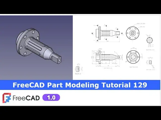
In this video I have explained How to Model Part in FreeCAD with the help of part design Workbench.
▶️ Visit my website for more info on FreeCAD-:
https://mechnexus.com/
▶️ Get my FreeCAD Crash Course for beginner-:
https://www.udemy.com/course/freecad-course-for-beginner/?referralCode=3BA9B526A12F96295D44
▶️ Download Source File of Tutorial-:
https://mechnexus.com/mechnexus-youtube-tutorial-source-file/
▶️ Buy Me a Coffee
I am very grateful that you watch my videos and I am constantly trying to improve the quality of the videos on this channel. If you'd like to help me do this, please consider supporting me so that I can to continue to produce content for your enjoyment.
👉 Help support this channel by buying me a coffee: https://ko-fi.com/mechnexus
All donations will be used to purchase equipment to improve my productivity and increase the quality of the content that I produce. Your kind support will help to grow this channel. Even if it's just enough to buy me a coffee every little helps and this will be repaid in full through my sharing of knowledge.
Show More Show Less View Video Transcript
0:00
hello friends welcome to Fria tutorial
0:02
and in this tutorial we will model this
0:05
part as you can see that uh I have
0:08
already did it i have converted this
0:10
autographic view into the 3D model in
0:13
Frecad and you can see that uh reference
0:16
drawing isometric view is matching with
0:19
our frecad
0:21
part in this tutorial I will show you
0:24
from the scratch how you can create this
0:26
part and uh for this tutorial I am using
0:30
the freecad version 1.0 so you must have
0:34
at least free version 1.0 or
0:38
higher now I will uh close this file and
0:42
create a new file
0:47
you can also visit my website
0:50
macexus.com where I write articles and
0:53
tutorials on a freecad and you can also
0:57
access my 3D part library of a free CAD
1:02
you can download the part from here and
1:05
you can use in your projects with
1:08
modifications
1:10
you can also access my 2D drawing
1:14
library where you can u download this 2D
1:18
drawings and uh you can create 3D models
1:23
with respect to these
1:25
drawings you can also support me on
1:30
coffi.com you can buy me a cup of coffee
1:34
your small support will uh help this
1:36
channels to grow and it will motivate me
1:40
to create more awesome content on uh
1:43
free cat you can find my Kofi donation
1:46
page link in a video description as well
1:50
as you can also see my Kofi page URL on
1:53
this
1:55
header so let's come back to our
1:58
tutorial
2:02
so here I have created a new file and uh
2:05
I have activated my part design
2:08
workbench and here I will insert the
2:11
body and I will on my origin
2:14
plane now if we see the isometric
2:20
view so we will create our base profile
2:23
on a front plane
2:26
so I will uh select this exit plane and
2:29
uh click on the
2:31
sketch and now switch to the model tab
2:34
and I will hide my
2:36
origin and
2:40
now I will uh create this half
2:45
profile and then I revolve it so for
2:49
this I will uh use the polyline tool and
2:53
uh I will uh create a rough profile
3:15
now I will uh make this
3:20
vertical and now we will uh rate the
3:24
dimensions and we will constrain it so
3:27
first dimension which I will give is uh
3:30
horizontal dimension which is uh
3:34
80.5 and
3:36
now I will
3:39
uh move my
3:44
sketch and uh
3:46
let's constrain this so this is the
3:50
diameter
3:53
28 so this will become
3:57
14 and uh from this point to this point
4:01
is of uh 22.5
4:06
and
4:11
now let's move the
4:16
dimensions and select the spot dimension
4:19
this is of a 10
4:23
mm 10
4:29
and I will move it
4:33
and this is of a
4:41
5.5 let's move the dimension this so
4:44
this is the five and this is
4:50
5.5 and
4:53
now this diameter is of a
4:56
12 so this will be the six
5:03
and from here to here is of 15
5:09
mm and from this dimension is of a 10
5:14
mm and this to this is of
5:18
a 10
5:23
mm so we have
5:25
given the dimension with respect to the
5:29
dimension given in a section a a
5:34
and now we will uh revolve
5:39
it so I will go to the models tab and
5:42
click on the
5:44
close from here I will switch to the
5:47
isometric and now I will select the
5:50
sketch and click on the
5:53
revolve but here we will define our
5:56
revolution from the x-axis so here I
5:58
will click on select reference and
6:01
select this
6:04
axis
6:06
now we will move to the next step so if
6:10
you see here in a side view so there is
6:14
a cut which we can see here so we will
6:18
select this phase and click on the
6:21
sketch and uh from here I will switch to
6:24
the isometric view and
6:28
now to create this cut I will uh project
6:32
this outer diameter click on project
6:35
geometry switch to the right plane and
6:39
now I will uh use the threepoint
6:47
arc create an arc and now I will select
6:52
the line
6:54
tool and uh create a
6:57
line and now we will read the
7:02
dimensions so from this point to the
7:06
origin is of a 4
7:17
mm which we can see
7:20
here now we will close it and uh we will
7:26
create a cut at a distance of 12 mm
7:30
so select the sketch click on the cut
7:34
and say it uh 12 mm and say
7:38
okay now if we see in isometric view so
7:42
this cut is mirror on the other side so
7:46
I will select the pocket and click on
7:49
the mirror tool and from here I will
7:52
click on select reference and uh select
7:55
this mid plane and say okay
7:59
now here I will uh save my
8:09
part now we will uh proceed to the next
8:12
step and our next step is to create the
8:18
cut which is on the back
8:21
side of our model so I will rotate my
8:27
model and I will select this face and
8:30
click on the
8:31
sketch and I will switch to the
8:34
isometric
8:36
view and uh now here I will uh create a
8:49
circle and now
8:51
the dimension of this circle is of 15
8:57
mm which we can see here diameter 15 and
9:01
this is the
9:02
17.5 so I will select the
9:06
diameter give it 15 and now
9:10
here I will uh create a
9:14
rectangle and I will
9:17
uh click on the trim tool trim this
9:24
this and now
9:27
here I will create a line and I will
9:31
make it a
9:33
construction select it and make it
9:36
construction and now make it uh
9:40
tangent select this point and axis and
9:43
add a coincidence now here we will give
9:46
this 17.5 dimension select it and
9:51
uh give it a
9:54
17.5 and
9:56
now this is of a 4 mm which we can see
10:01
here so first I will make it symmetric
10:04
select this point this point and this
10:07
axis select smart
10:10
dimension and give it 4 mm so now our uh
10:15
sketch is fully
10:18
constrained and now we will come out of
10:21
the sketch and we will create a cut at a
10:24
distance of 13 mm so here we can see
10:28
that depth is of 13 mm so select the
10:31
sketch click on the pocket and provide
10:34
the depth 13
10:38
mm now let's uh move to the next step
10:42
our next step is to create a datim plane
10:47
at a distance of 10
10:52
mm so I will on the origin
10:58
plane because we wanted to create this
11:01
cut and this diameter is of 20 so I will
11:05
select this uh XY plane and click on the
11:09
datm and in a Z
11:12
directions I will give the 10
11:16
mm so you can see that it is a tangent
11:20
plane on the surface click on
11:23
okay switch to the isometric and off the
11:28
origin plane and now we will create our
11:32
feature on this data plane so here is a
11:36
rebuild symbol right click it and click
11:39
on recomp compute object now select the
11:42
data plane and click on the
11:46
sketch now
11:48
here first we will switch to the
11:50
isometric to know the current
11:52
orientation so this is the top view here
11:56
we will uh create the slot so I will
11:59
simply select a slot
12:02
tool and create a slot and now I will
12:06
hide this data
12:08
plane and here I will uh project this
12:14
age and let uh switch to the flat lines
12:19
and now center to center distance is of
12:25
25 you can read this dimension here so I
12:29
will select smart
12:31
dimension and provide the center to
12:34
center dimension
12:35
25 and this is the
12:38
radius
12:40
2.5
12:42
and from here to this origin is of 6 mm
12:50
now I will close
12:53
it and I will create a cut of 1
12:58
mm because this is the diameter 20 and
13:01
this is the 18 so if we subtract it so
13:05
we will get 11 1 mm on both the side so
13:08
click on the cut and give the depth 1 mm
13:15
and now
13:17
here we are seeing the taper so which
13:21
will will be added in our uh cut so here
13:25
is a taper angle and here I will give
13:28
the minus
13:30
45 so you can see that taper has been
13:33
added
13:34
here say
13:36
okay now we will uh polar pattern
13:41
it so select it and click on the polar
13:45
pattern and from the axis I will select
13:49
my reference this
13:51
x-axis and uh number of uh instances is
13:56
of
13:58
eight and click on
14:04
okay so you can see that uh we have
14:07
created this cut
14:11
now we will uh create this
14:15
hole which is
14:17
of six hole of M5 at a PCD of 36 so I
14:24
will select this phase and click on the
14:27
sketch and from here I will switch to
14:31
the
14:32
wireframe and uh I will select the
14:37
circle create a circle and I will uh
14:41
make it uh as a
14:43
construction and uh I will uh make it
14:48
36 and now I will uh create a hole of M5
14:54
because this is the M5 tab so I will
14:58
create one uh circle
15:01
here and I will give it a 5
15:05
mm and now I will select this origin
15:09
point and this construction diameter and
15:12
add a coincidence select this and this
15:16
and add a coincidence so here is a M5 is
15:20
added and now let's uh switch to the
15:23
flat lines
15:26
view and now we will select the sketch
15:29
and we will use the whole
15:31
tool and here ISO metric regular profile
15:36
and from here I will uh select my tap
15:39
size which is of
15:42
M5 and uh from here I will uh say it uh
15:46
through
15:47
all and say
15:50
okay now we will polar pattern it select
15:54
the hole and click on the polar
15:58
pattern and uh here I will define the
16:02
quantity
16:06
six say
16:10
okay so now if we see
16:15
here from the cut this and this hole are
16:18
the on the line so we will delete our
16:22
uh we will edit our uh sketch so in this
16:27
case what we will do uh we will switch
16:30
to the right view and here is a
16:33
coincidence
16:35
constraint which I will delete it so
16:38
that
16:39
uh it is free to move and
16:43
now as per orientations this hole should
16:46
be horizontal so I will select the axis
16:51
add a coincidence and
16:53
then add a coincidence now click on
16:57
okay so here you can see that uh now our
17:02
whole position is matching because here
17:05
is the angle of
17:12
4545 so
17:16
now we will uh proceed to the next
17:22
step our next step is to provide the
17:26
fillet if you see our
17:29
model here so there are the fillet is
17:34
given so I will press the control key
17:37
and uh select these two edges and
17:41
uh give the fillet of uh R1 and say
17:48
okay now switch to the isometric so you
17:52
can see that uh we have
17:55
a successfully made this model and uh
17:59
there are the some small small thing
18:01
like here is a chamfer of a
18:03
0.5 so I will select these two edges and
18:08
uh provide the chamfer of uh
18:12
0.5 say
18:17
okay and uh there are the some areas
18:21
where uh you can add the minor things
18:24
like giving the fillet so here is a
18:26
chamfer of 1 mm at this age so I will
18:31
provide the CH
18:33
for and give it to 1
18:37
mm say
18:39
okay so you can see that we have
18:43
successfully modeled this part in a free
18:46
CAD with the help of a part design
18:48
workbench and uh we have
18:52
a some uh small features which you can
18:56
add like uh here is a revolve cut of a
19:00
DI 4 which is uh very easy to
19:05
do let me also create this profile so
19:08
here uh it is very simple i will select
19:11
this uh mid plane and click on the
19:14
sketch and uh I will
19:18
uh make it
19:20
wireframe and at the same time of the
19:23
origin and now here I will click on the
19:26
project
19:28
geometry and uh I will uh create a
19:33
triangle it is very simple just uh
19:36
create a triangle and uh use the revol
19:44
cut so
19:46
now this is the dimensions 2
19:49
mm 2 and four so I will select it and
19:55
give it two and
19:59
uh this is also
20:03
two and now I will close
20:06
it and let's uh switch to the flat
20:13
lines once uh switch to the shaded and
20:16
then switch to the flat lines and now
20:19
here I will select the sketch and click
20:21
on the
20:23
groove so here I want to define my axis
20:28
select
20:30
reference and select this X-axis
20:34
so you can see that uh cut has been
20:37
created with respect to our uh detail
20:41
e so this completes our model and uh
20:45
this tutorial is designed for the
20:47
beginner user of a free those who have
20:49
just started learning the part
20:52
modeling so this is all about the part
20:55
modeling with the part design workbench
20:58
thank you for watching and thank you for
21:00
your valuable time
#Computers & Electronics
#CAD & CAM
#Engineering & Technology
#Sculpture