Up next in 10


Explore PLC logic for controlling machines ON OFF functions via pushbutton input in industrial applications.
#machines #logic #plc
Tags:
plc programming, machine on off control, pushbutton switch, industrial automation, plc logic design, machine control plc, ladder logic, programmable logic controller, on off control, pushbutton operation, machine automation, plc example program, plc control system, on off switch logic, industrial machine control, automation control, pushbutton plc logic, plc input output, machine start stop control, plc tutorial, safety in machine control, plc ladder diagram
Show More Show Less View Video Transcript
0:13
welcome to automation Community today in
0:16
this video we are going to discuss an
0:18
example in which we will control three
0:21
machines using a single push button so
0:24
let's look at the example
0:27
first example 25 when switch is turned
0:30
on and then turned off then machine one
0:33
will be on and then when it when switch
0:36
is turned on and then turned off then
0:38
machine one will be off and Machine 2
0:41
will be on and then when switch is
0:43
turned on and then turned off then
0:45
machine two will be off and machine 3
0:47
will be on so there is a single push
0:49
button when it is first time pressed and
0:52
released machine one gets on and then
0:55
when it is second time pressed and
0:57
release machine one gets off and machine
1:00
2 gets on and then when it is third time
1:03
pressed and released Machine 2 becomes
1:06
off and machine 3 turns on so for this
1:10
example we will use normally open
1:12
contacts and normally close contacts we
1:16
will be also using some memory bits and
1:20
implementing some logic gates like or
1:23
and and we will be also implementing
1:27
Ling so let's move M to TI portal where
1:31
we will draw a ladder diagram for this
1:35
example so this is the interface of TI
1:38
portal firstly we will go to PLC tags
1:44
and then default tag table so here we
1:47
need to add our inputs and outputs we
1:49
have only one input that is
1:54
push
1:57
button and then we have some outputs
2:00
like
2:02
machine
2:04
one so this is an output so its address
2:07
will start with q and then
2:09
0.0 and then we
2:12
have two more machines Machine 2 and
2:16
machine3 their address will be Q 0.1 and
2:19
Q
2:20
0.2 and then we will go to program
2:23
blocks and then meain ob
2:27
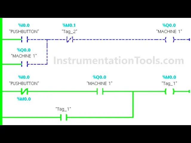
one so here we will be trying a lad
2:30
Logic for this
2:32
example so firstly we'll insert a
2:35
normally open contact for push
2:40
Buton and then I will insert a coil for
2:45
machine one so this will be machine
2:51
one and then I will add it
2:55
here so that when it is released machine
2:58
one Still Remains on I will open the
3:00
branch add a normally open contact and
3:03
then close the branch so this will be
3:05
machine
3:07
one and
3:11
then when the push button is released
3:15
and machine one is on then a memory bit
3:19
gets through and this memory bit will be
3:21
M
3:23
0.0 this is when push button is
3:27
pressed and M see one is on then M 0.0
3:33
gets through and we will latch it here I
3:35
will open the branch at a normally open
3:37
contact and connect it like this so this
3:40
will be M
3:43
0.0 and then when M 0.0 is true and push
3:49
button is once again pressed then a
3:52
memory bit gets on so this is M
3:57
0.0 sorry m0 0 and then this is push
4:02
button when it is once again
4:06
pressed then another memory bit gets
4:09
through that is M
4:11
0.1 and this will be last here open the
4:15
branch then add a normally open contact
4:18
and then close a branch so this will be
4:21
M
4:26
0.1 and then when M 0.0 gets through
4:31
and push button is released then Machine
4:36
2 gets
4:37
on so this is M
4:41
0.1 and this is when push button is
4:44
released
4:46
then machine two gets on machine two
4:50
gets
4:56
on and also when M 0.1 gets to then
5:00
machine one gets off so here we will use
5:02
a normally close contact for M
5:07
0.1 and
5:11
then when once again
5:15
when this uh M 0.1 is
5:19
true
5:27
and and then I will insert a nor close
5:30
contact
5:33
for push button
5:39
so so this is M
5:43
0.1 ma
5:46
2 is
5:48
on and switches released that is push
5:53
button is
5:56
released then another memory bits gets
5:59
to I will insert a coil and that coil
6:02
will be M
6:04
0.3 sorry M
6:07
0.2 and then we will latch it here open
6:11
the branch and a normally open contact
6:13
and then close the branch so this will
6:15
be M
6:17
0.2 and then when push button is again
6:22
pressed again pressed and this m 0.2 is
6:27
true then another memory bit gets
6:30
through so this is M sorry this is push
6:35
button it's once again
6:38
pressed and with that M 0.2 is true then
6:42
again one more memory bit M 0.3 gets
6:48
true and we will latch it here so I will
6:52
open the branch add a normally open
6:54
contact and then
6:56
close so this will be M 0.5
7:02
and this m
7:03
0.3 we used here as normally open
7:07
contact and M 0.3 gets through then
7:10
machine 3 gets on so this is M
7:14
0.3 and this is machine
7:18
3 with that when M 0.3 gets through
7:21
Machine 2 should get off so we'll use a
7:24
normally closed contact here for M 0.3
7:28
so when push button button is first time
7:30
pressed and release machine one gets on
7:33
and when it is second time release
7:34
Machine 2 gets on and machine one gets
7:37
off and when it is third time pressed
7:40
and released M 0.3 gets through which in
7:43
turn will make machine 3 on but it will
7:47
turn off Machine 2 I will start the
7:50
simulation here
8:15
after that let's start CPU okay and then
8:19
start
8:20
Monitor and after that I will sewitch to
8:23
project you
8:28
here let's create a new project here and
8:31
let's wait for some time
9:06
so I will go to simulation tables
9:08
simulation table one and then right
9:10
click here and load project
9:15
TXS so
9:19
now when push button is pressed and
9:23
released then machine one gets
9:27
on with that
9:31
this m 0.0 gets through and which will
9:34
turn M 0.1 when push button is second
9:37
time pressed and
9:39
released so when it is second time
9:42
pressed M 0.1 gets through and when M
9:46
0.1 gets two this push button is
9:49
released so this m 0.2 gets two and when
9:53
m0 point2 gets
9:57
through here Machine 2 gets
10:00
on this m 0.1 gets two and when M 0.1
10:04
gets true Machine 2 gets on but M 0.1
10:08
breaks the circuit here which in turn
10:10
will make machine one off and
10:22
then the M 0.2 is true here and then
10:27
when push button is again pressed
10:30
when it is again pressed M 0.3 gets
10:34
through
10:36
and which in turn will turn off the
10:39
machine 3 and if it is released machine
10:42
3 Still Remains on but this m
10:45
0.3
10:47
here will turn off Machine 2 so when
10:50
push button was pressed and released
10:52
machine one gets on and then when it is
10:54
second time pressed Machine 2 gets on
10:57
and machine one gets off and when it is
10:59
third time press and release machine 3
11:02
gets on and Machine 2 gets off it was
11:05
all about this example thank you for
11:07
watching
11:09
[Music]
#Manufacturing
#Jobs & Education
#Industrial Handling & Processing Equipment
#Factory Automation