Up next in 10

Learn the Adding Counters in PLC programming.
#Counters #PLCCounters #PLCProgramming #IndustrialAutomation #LadderLogic #ControlSystems #PLCTutorial #AutomationEngineering #PLCTraining #DigitalCounters #SiemensPLC
👇FOLLOW US👇
WhatsApp Channel: https://whatsapp.com/channel/0029VaAbUecLNSa4rDPOV31o
Telegram Channel: https://t.me/+u3qORX5FKec1NjA1
Instagram Page: https://www.instagram.com/instrumentationtools/
Facebook Page: https://www.facebook.com/instrumentationtoolss/
LinkedIn Page: https://www.linkedin.com/company/instrumentationtools/
YouTube Channel: https://youtube.com/instrumentationtools?sub_confirmation=1
Tags:
adding counters in plc, plc counters, plc programming, ladder logic counters, digital counters in plc, up counter plc, down counter plc, counter function block plc, plc count logic, event counting plc, industrial automation plc, control systems plc, plc tutorial for beginners, plc training, siemens plc counters, allen bradley plc counters, plc ladder examples, plc counter instruction, plc counter application, plc basics
Show More Show Less View Video Transcript
0:07
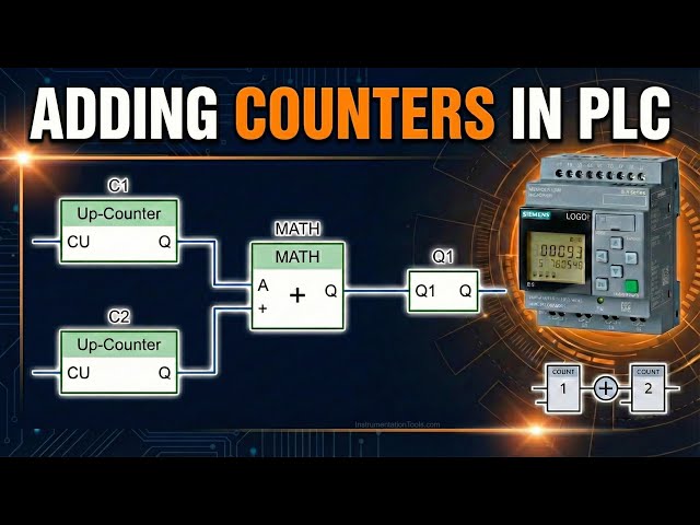
hello everyone myself badas in this
0:11
video I will discuss one simple
0:14
example which is addition of two
0:18
counters here we have two counters C1
0:22
and C2 we have to perform addition of
0:27
these two counter values
0:31
here we have two problems the problem
0:34
one is we have to do this calculation
0:37
addition of two counters with mathematic
0:41
block and the problem two is without
0:45
mathematic
0:47
block we already discussed about this
0:51
mathematic Block in the previous videos
0:54
so just pause the video here and try to
0:58
do the addition of two
1:01
counters let's continue to the video and
1:05
I go to the
1:07
software first I will take two
1:11
counters I will take this up down
1:17
counter
1:21
okay and I will connect one input to
1:27
this count
1:30
and one more input to the second counter
1:35
I will give the name the counter with C1
1:38
this is my counter
1:43
one and this is my counter
1:48
two
1:50
okay I'm not using reset Direction
1:54
inputs if you want you can connect and
1:56
check
1:57
also now
2:01
this counter output is digital output
2:04
which I am not using so I will connect
2:07
open
2:09
connector for simulation purpose it will
2:13
work even if you do not connect this
2:14
connector okay to download this program
2:17
into the PLC we have to connect the
2:21
output either to the digital output or
2:24
to this open
2:26
connector now I will take the mathematic
2:29
block so go to the analog section and
2:32
take the mathematic instruction
2:35
block there is one enable input so
2:38
either you have to connect one digital
2:40
input or I just
2:43
want status one I will take here if you
2:46
see under digital we can have status
2:49
zero status one okay I need always this
2:53
mathematic block to be in on state
2:56
enable state so I just us it high
3:00
now click the plus icon under the C1
3:04
counter one and counter
3:07
two similarly under mathematic
3:10
instruction block first give the proper
3:13
go to property and comment this is
3:17
mathematic instruction
3:20
block and the output is analog so I will
3:23
connect one analog flag also
3:36
okay now this C1 and this table the
3:41
first one is Count output this this
3:45
Conor is there right I will take this
3:47
and connect to the P1 of mathematic
3:51
block first input of mathematic block
3:54
similarly for C2 in this table the count
3:59
of output I will take and I will connect
4:02
to the
4:03
P2 P2 of mathematic
4:06
block now I'll go to the mathematic
4:09
block properties and you have to select
4:13
the operator I want C1 plus C2 that is
4:17
why we have to do the plus and we can
4:21
connect maximum four parameters here in
4:23
this properties in this mathematic block
4:27
so remaining two parameters just add 0 0
4:32
if you see the block one is added here
4:35
and block two is added here that means
4:37
C1 and C2 count values press
4:42
okay now I will go to the
4:47
simulation for the i1 go to properties
4:50
and select moment rep push
4:53
button and for I2 I'll go to the
4:57
simulation and select moment push button
5:01
now see I will press the i1 here one
5:06
time the counter value is increased by
5:08
one in C1 this one is also connected to
5:13
the mathematic block P1 so it is also
5:17
updated now the mathematic block will do
5:19
P1 + P2 addition of P1 P2 P3 P4 P3 P4
5:25
are 0 0 so ignore this now I will press
5:30
I2 also see one time what happened the
5:34
counter two value also increased by one
5:37
so both this C1 and C2 counter values
5:41
are updated in mathematic block P1 P2 P1
5:45
+ P2 1 + 1 that is equal to 2 I am not
5:50
talking about P3 P4 as they are 0 0 okay
5:54
now I will increase i1 I will give the
5:57
pulses see C1 is is
6:00
increasing same value will be updated in
6:02
mathematic block 6 + 1 7 like this we
6:07
can do the addition of two counters
6:12
using mathematic
6:14
block right very
6:17
simple see in the counter I'm not using
6:20
reset and Direction inputs you can also
6:23
connect digital inputs to these C1 and
6:27
C2 separately and and you can test your
6:32
logic
6:33
okay now the problem one is completed
6:37
now in problem two we have to do the
6:40
same operation without using mathematic
6:45
block so pause the video here again and
6:49
try to solve this problem without
6:53
mathematic
6:55
block now I'll continue the Click Click
6:58
Arrow
6:59
so I will come out of the
7:01
simulation now I'll keep this now I will
7:05
take analog
7:07
multiplexer so go to analog and select
7:11
analog
7:12
multiplexer I'll take two
7:17
multiplexers
7:19
okay and if you see one enable is there
7:23
so I will just use status high you can
7:26
also connect digital input if required
7:33
okay and S1 S2 I'm not using because I'm
7:37
using only the the first out first input
7:40
of
7:41
multiplexer so when S1 is z0 S2 is zero
7:44
the first input will be selected by
7:47
default so I'm not
7:50
using now what I will do I will connect
7:54
the C1 count value in multiplexor one
7:57
first input and the C2 count value I
8:01
will connect in second multiplexor first
8:04
input so in properties what I will write
8:08
this is my Max with C1 value
8:14
okay multiplexor one you can simply call
8:17
with C1 value and this one I'll call
8:21
multiplexor with C2 value counter one
8:24
value counter two value so for that
8:27
purpose what we have to do under this
8:30
first multiplexer click the plus
8:33
icon
8:38
okay now go to
8:41
C1 and count just select here and draw a
8:47
line and connect to P1 of first
8:50
multiplexer now if you see the counter
8:53
value C1 which is 13 here is updated in
8:58
multiplexer one P1 parameter
9:02
1
9:05
similarly click the plus symbol of
9:08
second
9:09
multiplexer and go to top and connect
9:12
the C2 count value which is right now
9:16
11 select here to S the wiring uh select
9:21
here and go to second multiplexor first
9:25
input connect the values are updated if
9:28
you see
9:35
right the P1 is updated multiplexor one
9:39
second multiplexor P1 is also updated
9:42
good now what I will do I will take one
9:47
analog amplifier
9:51
block and I connect C2 to this block
9:56
what this block do is
9:59
I will go to properties and in gain I
10:02
will enter
10:05
minus1 go to comment what I'm doing is
10:09
I'm taking C2 input I will multiply with
10:12
minus one so what I will get I will get
10:15
minus
10:16
C2 okay this is my output what is the
10:21
output of this block minus C2 now I will
10:25
take one analog comparator block okay I
10:28
will connect my first multiplexor output
10:32
to this first
10:33
input and the output of this analog
10:38
amplifier which is minus C2 I will
10:40
connect to the second
10:44
input okay
10:49
now the output of this analog comparator
10:52
I'm not using so I will just simply
10:55
connect One open connector
11:01
now what is this analog comparator will
11:03
do it will compare two values in this
11:06
case what are those two values the first
11:08
input is a i1 sorry the first input is
11:13
C1 minus the second input is minus
11:17
C2 so that is equal to what is the
11:20
calculation C1 + C2 so it will add these
11:25
two counter
11:27
values okay
11:30
so we will see this now go to the
11:35
simulation now all values are 0
11:38
0 I will give increase the counter
11:41
values C1 I will give two commands two
11:44
inputs so count value is two updated in
11:47
mathematic block also again it is
11:49
updated in multiplexor one also see
11:53
two similarly I will give input two
11:57
three times three triggers three inputs
12:01
the count value of C2 is three
12:05
so C1 is 2 C3 C2 is 3 in mathematic
12:10
block if you see 2 and three updated the
12:13
result is 2 + 3 5 this is our method one
12:18
in second method multiplexer also
12:22
updated two came in C1 and in C2 three
12:27
came right
12:30
now this analog amplifier what it will
12:34
do it will multiply the C2 with minus1
12:37
so as C2 is three the output of this
12:41
block is minus
12:43
3 okay now analog comparator will do C1
12:47
minus
12:48
C2 so which in this case it
12:52
is 2 minus again - 3 which is finally 2
12:59
+ 3
13:01
5 okay this is how we can do the
13:05
calculation of two counters addition
13:09
addition of two counters with mathematic
13:12
block one option without mathematic
13:15
block second option if you have any idea
13:19
or any way to do these addition of two
13:22
counters using any other blogs try
13:27
yourself and share with us through the
13:29
comment section okay you can also use
13:32
the reset and Direction and inputs in
13:35
the counters and test your logic share
13:39
with us if you found any other way
13:43
okay thank you I will meet you in the
13:45
next session
#Jobs & Education