Up next in 10

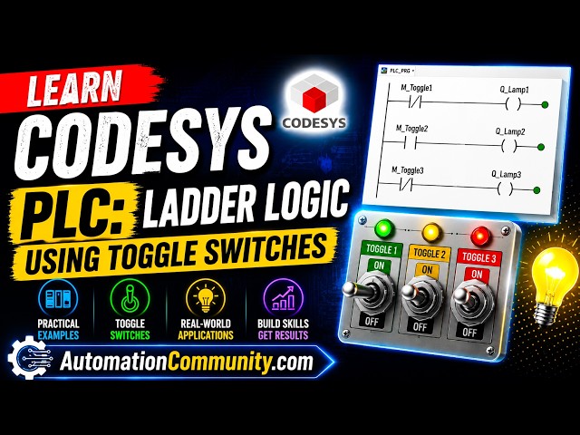
Learn CODESYS PLC ladder logic using toggle switches with practical programming examples for beginners.
** Video Topics **
0:00 Learn CODESYS
0:22 Program objective
1:07 CODESYS New Project
2:17 PLC Programming
5:49 Ladder Logic Explanation
6:45 Simulation of PLC Logic
✨ FOLLOW US ✨
👉WhatsApp: https://whatsapp.com/channel/0029VaAbUecLNSa4rDPOV31o
👉Telegram: https://t.me/+u3qORX5FKec1NjA1
👉LinkedIn: https://www.linkedin.com/company/instrumentationtools/
👉Facebook: https://www.facebook.com/instrumentationtoolss/
👉Instagram: https://www.instagram.com/instrumentationtools/
👉YouTube: https://youtube.com/instrumentationtools?sub_confirmation=1
👉JOIN Courses: https://automationcommunity.com/
#codesys #training #ladderlogic
Show More Show Less View Video Transcript
0:00
[Music]
0:06
Hello everyone, welcome to automation
0:09
community. Today in this video we are
0:12
going to discuss an example in which we
0:15
will be controlling port solenoids using
0:18
two toggle switches. So let's start.
0:22
Example nine. If toggle switch one is on
0:25
then solenoid one and solenoid 2 will be
0:28
on. If toggle switch one is off, then
0:31
solenoid one will be off and solenoid 2
0:35
will be on. If toggle switch two is on
0:38
then solenoid 3 and solenoid 4 will be
0:41
on. If toggle switch 2 is off, then
0:44
solenoid 3 will be off and solenoid 4
0:47
will be on.
0:50
So for this example we will use normally
0:53
open cuts and with that we will be using
0:57
some set coils and normal coils. So
1:00
let's move to codices where we will draw
1:03
a ladder diagram for this example.
1:07
I will open codices.
1:18
Firstly, we need to create a new
1:20
project. Let's create a new project. And
1:23
we can set the name of the project and
1:25
select the location here. So for now, we
1:28
will keep the name as example 9.
1:34
Example 9. And we need to set this
1:38
template as standard project. And click
1:40
on okay.
1:42
Here
1:44
we can set the programming language from
1:46
this list and for now we will be using
1:49
latter logic diagram and we we can also
1:52
select the device from this uh drop-own
1:55
list and click on Okay.
2:16
Let's go to PLC programming here. Double
2:19
click on it. And here we will draw the
2:21
ladder diagram.
2:23
Firstly, we will insert
2:26
a normally open contact for toggle
2:29
switch one. Let's write toggle switch
2:33
one.
2:41
Toggle
2:43
switch one. Okay. And then we will
2:48
insert
2:49
a set coil for solenoid one. So we'll
2:52
insert a set coil here and we will write
2:56
solid
2:58
one and then we need to insert one more
3:02
coil for solenoid 2. So we will insert a
3:06
branch below and add a simple coil here
3:10
for solid
3:13
2.
3:16
So we have used a set coil for solenoid
3:18
one and we have used a normal coil for
3:21
solid 2. Why? Because when toggle switch
3:25
one is turned on both the solenoid
3:29
solenoid one and solenoid 2 should turn
3:32
on and then when toggle switch one is
3:36
turned off solenoid one should remain
3:39
on. So to keep the solenoid one on even
3:44
when we turn off the toggle switch one.
3:48
So we use a solenoid
3:51
uh we use a set coil for solenoid one.
3:53
So this set coil will keep the solenoid
3:56
one on even when we turn off the toggle
3:59
switch one and the solenoid 2 for this
4:02
solenoid 2 we have used a normal coil.
4:05
So when we will turn off toggle switch
4:07
one solen I2 will also turn off. But the
4:11
solenoid one will remain on when we turn
4:14
off to switch one because of the state
4:16
coil we have used for this solenoid one.
4:20
Let's insert one more network below this
4:23
and we need to insert same and normally
4:26
open contact but that will be for toggle
4:30
switch two.
4:32
Okay. And then we need to insert a set
4:36
coil
4:37
for
4:39
this uh
4:42
for this uh uh sorry solenoid 4. So we
4:46
will insert a set coil for solenoid 4.
4:49
Solenoid
4:52
4.
4:56
Okay. And we need to you know open the
5:00
branch insert a branch here and add a
5:02
normal coil for solenoid 3. So this is
5:06
solenoid three. So here we will uh sorry
5:11
we will delete this
5:13
also this. So here
5:17
we will insert a coil
5:20
uh sorry we will insert a set coil here
5:23
a set coil and here a normal coil. So
5:27
the set coil will be used for soleno I2
5:31
solenoid 2
5:38
and a normal coil will be used for
5:41
solenoid one.
5:48
Okay. So when toggle switch one is
5:51
turned on solenoid one and solenoid 2
5:54
both turn on. And when toggle switch one
5:57
is turned off, toolenoid one will turn
5:59
off because we have used a normal coil
6:02
for it. But the solenoid 2 will remain
6:04
on because we have used a set coil for
6:07
this. Similarly, when toggle switch two
6:09
is turned on, both the solenoid solenoid
6:12
3 and solenoid 4 will turn on. But when
6:15
we will turn off the toggle switch two,
6:19
solenoid 3 will turn off because we have
6:22
used a normal coil for the solenoid 3.
6:25
But solenite 4 will remain on because we
6:28
have used a set coil for solite 4. So it
6:31
will remain on. And now let's check
6:35
code.
6:37
Go to online and start simulation.
6:40
Let's log in.
6:42
Yes.
6:45
And then start.
6:48
Okay. For now both the toggle switches
6:50
are off. So is the case with the
6:52
solenoid. All the solenoid lines are
6:54
off. So when I turn on so toggle switch
6:58
one. So we need to click here turn it
7:00
through and then go to debug and write
7:02
values. So you can see here when I
7:05
turned on this toggle switch one
7:08
solenoid one and solenoid 2 both the
7:11
solenoids got blue. Both the solenoids
7:14
are on. And then when I turn it off I
7:17
click here and the false appears here.
7:21
And then we will go to debug and write
7:23
values. And you can see here solenoid
7:26
one gets off. But the solenoid 2 is
7:29
still true. Why? Because we have used a
7:32
set coil for the soil 2. So the soil 2
7:36
remains on when we turned off this
7:39
toggle switch one. Similarly when we
7:43
turn on this toggle switch two. So uh
7:46
click here. Make it true here. make uh
7:49
make it make a true appear here and then
7:51
go to debug and write values. You can
7:54
see here soil night 3 and so light 4
7:56
both gets on. But when we will turn off
7:59
this uh toggle switch two go to debug
8:02
and write values. You can see here soil
8:05
night 3 gets false. Solenite 3 gets off
8:08
but the solenite 4 remains on because of
8:10
the set coil we have used for this
8:13
solenite. So the set coil keeps that
8:16
output as true even when the the input
8:20
gets off. It was all about this example.
8:23
Thank you for watching.
8:26
[Music]
#Science