Up next in 10

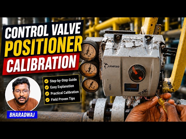
Understand how to calibrate control valve positioners used in process control and instrumentation systems.
** Video Topics **
0:00 Control Valve Calibration
1:11 Valve Positioner
1:46 Mode Selection
2:22 Automatic Calibration
2:52 Inbuilt Algorithm
3:12 Instrument Air Supply
3:47 Valve Status
4:09 Valve Stem Movement
4:21 Calibration Types
4:53 Valve Display
5:16 Calibration Successful
✨ FOLLOW US ✨
👉WhatsApp: https://whatsapp.com/channel/0029VaAbUecLNSa4rDPOV31o
👉Telegram: https://t.me/+u3qORX5FKec1NjA1
👉LinkedIn: https://www.linkedin.com/company/instrumentationtools/
👉Facebook: https://www.facebook.com/instrumentationtoolss/
Show More Show Less View Video Transcript
0:07
Hello everyone. Myself Bharadwaj. In
0:10
this video, I will show you how to do
0:13
foundation field bus control valve
0:15
calibration using valve positioner
0:19
display.
0:21
Now first, I will remove the four screws
0:24
here and then I will remove the front
0:27
cover.
0:28
So that I can access the valve
0:31
positioner display. This is a small
0:33
display
0:34
mounted on the valve positioner.
0:38
You can do the configuration. You can do
0:39
the calibration from this display.
0:43
Okay?
0:45
You can also connect your hot
0:46
communicator and you can do the same
0:48
function.
0:50
But in some models, we have valve
0:53
display available on the valve
0:56
positioner itself.
0:59
Remember,
1:00
uh you can do the
1:02
uh calibration using this display such
1:05
that it will save some time for you. The
1:08
hot communicator takes time. Remember
1:10
that. That is why we prefer
1:13
calibration from this small display.
1:17
You can see here, right now it is
1:19
showing some values here.
1:22
Some are pressure signals, temperature
1:24
values, right?
1:27
See?
1:28
This is supply pressure, 2.3 kg.
1:31
And we have
1:33
four buttons here on the display.
1:35
This is positive. This is positive,
1:37
negative. This is enter. This is cancel.
1:41
Okay?
1:43
So now I need to go to mode. So I will
1:46
press the minus and the plus at a time.
1:50
It will go to the
1:52
mode.
1:54
Okay? Now I will press enter.
1:57
Now I have to select auto or manual. I
2:00
will select auto.
2:02
Okay.
2:04
I need auto, so I press auto and enter.
2:08
See, now we are in mode and we can see
2:12
the available options here by pressing
2:14
minus or plus. I will press plus. See,
2:19
parameter calibration. Okay, I need to
2:22
go to calibration, enter, auto
2:24
calibration, enter.
2:26
That's it. The calibration is started.
2:28
You can see the status here. The wall
2:31
will automatically move the stem at the
2:34
different points.
2:36
Remember, you can see the calibration
2:38
status on the display. Now it is showing
2:41
cal one.
2:43
It has to reach cal 100.
2:46
Whenever it reaches cal 100, that means
2:49
the automatic calibration is completed.
2:53
See, the wall positioner have inbuilt
2:55
algorithm so that when we select
2:58
automatic calibration
3:01
uh as per the algorithm, it will move
3:04
the wall system at different locations.
3:06
That means different points. And then it
3:09
will adjust the feedback accordingly.
3:12
Remember, the wall positioner receives
3:14
the instrument air supply.
3:16
So you can see the gauges here, the
3:18
pressure gauges. You can see the inlet
3:21
instrument air, outlet instrument air,
3:23
right? Outlet means instrument air going
3:26
from the wall positioner to the
3:28
actuator. So the wall positioner
3:32
regulates or controls the instrument air
3:35
supply, right? That is why you can see
3:38
the pressure gauges here. They are not
3:41
constant. Their pointer is moving. That
3:43
means the instrument air supply is
3:45
regulating. Right? And on top of the
3:48
wall positioner, you can see See small
3:50
knob with red
3:53
This is also indicates the valve open
3:55
percentage or closed percentage, right?
3:58
That means open status or closed status.
4:01
Right now, the status is cal 44. It
4:04
reached 44.
4:06
It has to reach 100.
4:09
Okay, you can see the valve stem
4:10
movement clearly.
4:12
The valve positioner regulating the
4:14
instrument air flow.
4:16
Remember, you can do this calibration
4:18
from three locations in Foundation
4:20
Fieldbus. The first one is
4:23
valve positioner display. I'm talking
4:25
with respect to control valves. The
4:27
second one using your heart
4:28
communicator. The third one using your
4:32
remote computer. If you have a valid
4:34
license and hardware, you can perform
4:38
these actions from your remote computer
4:40
also. You can give a
4:42
control valve calibration command from
4:44
your remote computer in your control
4:47
room.
4:48
Now, the status is cal 75.
4:51
Remember,
4:53
when you have a valve positioner
4:54
display, it is the recommended method to
4:57
do the calibration from this display.
5:01
Because your heart communicator may take
5:03
some time.
5:05
For a maintenance plant, we usually do
5:08
use the
5:09
available display. If there is no
5:12
display available, then only we use
5:14
heart communicator. The calibration is
5:16
completed. You can see the message here,
5:18
calibration successful.
5:22
Okay.
5:23
The calibration may take some time.
5:25
Remember that, it may take two to five
5:27
minutes depending on your valve design.
5:31
So, by using this simple small display
5:35
on the valve positioner, we can complete
5:37
the calibration.
5:40
Remember, if you need some advanced
5:42
features, advanced diagnostic messages,
5:45
then we have to use our heart
5:47
communicator.
5:48
For normal maintenance purpose, we can
5:51
use this display.
5:53
If you have any questions, please share
5:55
with us.
5:57
Do like our videos, share our courses
5:59
with your colleagues and friends.
6:03
Thank you. Thank you for your
6:05
support.
#Science