Up next in 10

Learn a CODESYS PLC automation project using Four LEDs and ladder logic programming. This practical example demonstrates how PLC logic controls multiple LED outputs, how input conditions affect output states, and how ladder diagrams are developed in CODESYS for automation training and learning purposes.
✨ FOLLOW US ✨
👉WhatsApp: https://whatsapp.com/channel/0029VaAbUecLNSa4rDPOV31o
👉Telegram: https://t.me/+u3qORX5FKec1NjA1
👉LinkedIn: https://www.linkedin.com/company/instrumentationtools/
👉Facebook: https://www.facebook.com/instrumentationtoolss/
👉Instagram: https://www.instagram.com/instrumentationtools/
👉YouTube: https://youtube.com/instrumentationtools?sub_confirmation=1
👉JOIN Courses: https://automationcommunity.com/
** Video Topics **
0:00 Automation Project
1:45 CODESYS Project
2:50 LEDs programming
4:08 Toggle Switch 2
6:02 Memory Bit
6:55 Project Explanation
8:29 Project Simulation
Show More Show Less View Video Transcript
0:00
[Music]
0:07
Hello everyone, welcome to automation
0:10
community. Today in this video we are
0:13
going to discuss an example in which we
0:16
will be controlling four LEDs using two
0:19
toggle switches. So let's look at the
0:22
example first.
0:24
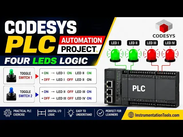
Example 11. If toggle switch one is on
0:27
then LED one and LED 2 will be on. If
0:31
toggle switch one is off then LED one
0:34
will be off and LED 2 will be on. If
0:37
toggle switch two is on then LED 2 will
0:41
be off and LED 3 will be on. If toggle
0:45
two or switch two is off then LED 3 will
0:48
be off and LED 4 will be on. That means
0:53
we have four LEDs and two toggle
0:56
switches. And when toggle switch one is
0:58
turned on, LED one and LED 2 both turn
1:02
on. And when it is turned off, one LED
1:04
turns off but the other LED remain on.
1:07
And that LED 2 will be turned on using
1:10
toggle switch two. And third LED turns
1:12
on. And that third LED is turned gets
1:16
turned off when that toggle switch two
1:19
is turned off. And with that LED 4 turns
1:22
on.
1:23
So for this example we will be using
1:26
normally open contacts uh normal coils
1:29
and we will be also using subset coils
1:32
and reset coils. With that we will be
1:35
also using memory bits and normally
1:38
closed contacts. So let's move to
1:40
codices where we will draw a ladder
1:43
diagram for this example.
1:45
So I will open codices.
2:20
So firstly we need to create a new
2:22
project.
2:24
Click on new project.
2:27
We can uh uh type the name of the
2:30
project here and we can also select
2:32
template as data project and click on
2:34
okay.
2:39
After that we can also select device and
2:41
PLC programming. So we will be uh using
2:45
ladder logic diagram and click on okay.
2:50
After that double click on this PLC
2:52
programming. So here we will be drawing
2:54
ladder diagram. So firstly we will
2:57
insert a normally open contact for
2:59
toggle switch one. So this will be
3:01
toggle
3:03
switch one and this toggle switch one
3:07
will turn on LED 1 and LED 2. So we will
3:10
insert a coil. This coil will be for LED
3:15
one.
3:17
And there will be one more coil for LED
3:20
2. But for LED 2 we will use a set coil.
3:23
Before that we will insert a branch and
3:26
add a set coil. So this set coil will be
3:29
for LED 2.
3:34
Okay. So this will be LED one.
3:44
Okay.
3:46
So we will delete this LED here.
3:54
Okay. So when toggle switch one is
3:56
turned on, LED one and LED 2 both gets
4:00
on. And when this le uh when this toggle
4:02
switch one is turned off, LED 1 gets off
4:05
but LED 2 remains on. And after that we
4:10
have one more toggle switch. For that we
4:11
will insert network below here. And we
4:14
will insert a normally open contact for
4:17
toggle switch one. Sorry for toggle
4:20
switch two. So this toggle switch two
4:24
will turn off LED 2. So for that we will
4:28
insert a reset coil here and this reset
4:31
coil will be used for LED 2.
4:38
So this will be LED2
4:45
LED 2. Okay. So this toggle switch two,
4:57
this toggle switch two will turn off LED
5:00
2.
5:05
And after that this uh toggle switch two
5:08
will turn on LED 3 as well. For that we
5:12
will insert a branch here
5:16
and add one more coil a normal coil here
5:21
which will be le 3. LE3.
5:26
Okay.
5:28
After that
5:32
we will insert one more branch here
5:38
and for that we will insert a coil. That
5:40
coil will be used as a memory bit. But
5:43
this coil will not be a normal coil but
5:46
a set coil that will be used for a
5:48
memory bit
5:51
for a memory bit. Okay. So this memory
5:55
bit will be used to turn on LED 4 on
5:58
turning off the toggle switch too. So we
6:01
will insert network below here and we
6:04
will insert a normally open contact for
6:08
this memory pair. So this will be memory
6:11
bit
6:13
and this memory bit will turn on LED 4.
6:17
For that we will insert a coil. So this
6:20
will be LED 4. But this LED 4 will turn
6:24
on when uh toggle switch is turned off.
6:28
After
6:30
uh uh so firstly we need to turn on
6:32
toggle switch two and then we need to
6:34
turn off the toggle switch two then the
6:36
LED 4 will turn on. So for that we will
6:39
insert a normally closed contact for
6:42
toggle switch two.
6:46
Okay. Great. So when toggle switch one
6:49
is turned on LED one gets on because
6:52
this toggle switch one.
6:56
So when this toggle switch one is turned
6:58
on this is a contact normally open
7:00
contact. When it is in true state the
7:02
the signal will pass through this. As a
7:04
result, this LED one gets on and also
7:07
this LED 2 gets on. And then when toggle
7:10
switch two is turned off, the signal
7:12
will not pass through this. As a result,
7:14
this LED one gets off. But this LED2
7:17
remains on because of the set coil we
7:19
have used for LD2. So the set coil keeps
7:22
the output on even when uh when we turn
7:24
off the input. And then when we turn on
7:28
the toggle switch two, the signal will
7:30
pass through this and it will reset LED
7:33
2 because we have used a reset coil
7:35
here. So LED 2 gets off but LED 3 gets
7:39
on. Okay. So with that this memory bit
7:43
gets true but the current sorry the
7:46
signal will not pass through this. As a
7:48
result this LED 4 will not turn on
7:50
because the toggle switch two is on. So
7:53
the signal will not pass through this.
7:55
But this memory bit gets true. So the
7:58
signal will pass through this. But this
8:00
toggle switch two is still true. As a
8:03
result, this LED 4 is still false. So
8:06
when we will turn off this uh switch to
8:08
toggle switch two, this LED 3 gets off.
8:11
But this memory bit remains true because
8:13
of the set coil, it keeps the that
8:15
memory bit true. Uh even when we turn
8:18
off this toggle switch two. So this
8:21
memory bit is true and this toggle
8:22
switch two is false. So the signal will
8:24
pass through this. As a result, this LED
8:27
4 gets through.
8:29
So we will generate code.
8:35
Go to online
8:37
start simulation. And after that we need
8:39
to log in.
8:42
Yes.
8:47
And then start.
8:50
So firstly when I turn on toggle switch
8:52
one click here make it true then go to
8:54
debug and write values. You can see here
8:57
LED one and LED 2 both turned on but
9:01
when I uh and when I turned off this
9:03
toggle switch one go to debug and write
9:06
values. LED 1
9:09
turned off but LED 2 remained on because
9:11
of the set guid. And then I need to turn
9:15
on the toggle switch to keep it true and
9:18
then go to debug and write values. You
9:20
can see here LED 2 got false because of
9:23
the reset coil which was turned on by
9:26
toggle switch two. So this reset coil
9:29
made the LED 2 to go off and with that
9:32
this LED 3 got on and also this set coil
9:37
uh this set coil for memory bits.
9:40
And when I turn it off, when I turn off
9:43
toggle switch two here, I will debug it
9:46
and write values. This set coil keeps
9:48
this memory bit true. And the signal
9:50
flows through this. And this toggle
9:52
switches false. So the signal also
9:55
passes through this. As a result, this
9:57
LED gets true. It was all about this
10:00
example. Thank you for watching.
10:03
[Music]
#Science