0:07
Hello everyone myself Baradwas.
0:12
In this course I will explain about
0:16
foundation field bus protocol.
0:20
This is a digital communication
0:24
Using this we can send the field
0:29
instruments data to the DCS system using
0:35
digital communication.
0:39
I will explain how this digital
0:47
advantages, disadvantages,
0:50
live system configuration,
0:54
realtime images and videos. I will show
0:58
you so that you will understand about FF
1:04
the short form is FF foundation field
1:10
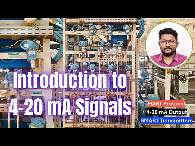
Before going into the foundation field
1:13
bus, let's discuss about the present the
1:22
and these are 4 to 20 milliamp based
1:26
signals which we are using to handle
1:33
We are using 4 to 20 milliamp signals
1:39
field instruments and DCS system.
1:43
If you see here, this is a temperature
1:47
transmitter. This is a pressure
1:49
transmitter and this is a DP
1:53
These instruments measures the
1:56
respective process parameter
2:00
like temperature, pressure, flow, level
2:07
and then generates an equivalent 4 to 20
2:12
milliamp basis signal.
2:15
These instruments sends 4 to 20 milliamp
2:19
based signals to the DCS system.
2:24
The DCS system receives these signals
2:28
and calculates the equivalent process
2:33
So these are the measurement signals
2:36
which we are using in our control
2:41
This is the uh very popular
2:46
and industry standard.
2:50
So let us see how this 4 to 20 millia
2:53
signals works in a brief way. Okay. I
2:57
will take one example.
3:00
Let's say we have a tank and I want to
3:04
measure this tank level. Then I need one
3:13
This level transmitter measures the tank
3:16
level and sends equivalent 4 to 20
3:28
This is the analog input.
3:32
And then the DCS system
3:36
updates this measurement to the
3:38
operators on the computer screen. Right?
3:44
The communication between the DCS system
3:50
generally through Ethernet based
3:54
We have some other protocols also
3:56
available. Let's stick to the Ethernet
4:02
Let's say I have a tank level of
4:07
0%. There is no level in the tank.
4:12
The level transmitter measures this tank
4:15
level and generates equivalent
4:21
As the range starts from 4 to 20
4:24
miampere, the minimum range is 4
4:27
miampere and the maximum range is 20
4:32
Right now the tank level is 0
4:35
percentage. That means it will send the
4:38
minimum current output to the DCS
4:41
system. What is the minimum output? It
4:49
and then DCS updates this tank level to
4:55
Let's say the tank level increased to
5:01
Then again the transmitter calculates
5:04
the tank level and sends equivalent
5:08
current signal which is 8 milliampere.
5:13
Then this system updates the tank level
5:15
which is 25% to the operator graphics.
5:22
Let's say tank level increases to 50%.
5:25
The equivalent current signal is 12
5:29
and then again this updates this tank
5:32
level to the operator.
5:36
Again tank level increases to 75%.
5:40
What is the current output? It is 16
5:43
miampere current signal and again DCS
5:47
updates this reading to the operator.
5:51
Let's say tank level reaches maximum
5:54
What is the maximum current output? It
6:00
Again the DCS receives this 20
6:02
milliampere and then calculates the tank
6:05
level and updates to the operator.
6:10
See this is the popular and industry
6:15
which we found in every industry. Now
6:20
this complete analog signals are handled
6:23
using 4 to 20 millia based current
6:27
We are also using this 4 to 20 milliamp
6:30
based current signals for the control
6:37
to control the motor speed.
6:41
So analog inputs and analog outputs
6:45
these are mostly 4 to 20 millia based
6:50
We have other signals also available
6:53
but this is the most standard signal in
7:03
I will explain digital communication
7:07
alternative for these analog signals. So
7:10
this is the most fundamental basic
7:13
concepts for a engineer working with
7:19
Thank you. I will meet you in the next