0:05
Hello everyone, welcome to automation
0:08
community. Today in this video we are
0:12
going to discuss an example in which we
0:14
will use set coils. So let's start.
0:20
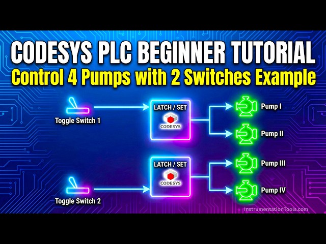
Example seven. If toggle switch one is
0:22
on then pump one and pump two will be
0:28
If toggle switch one is off, then pump
0:30
one and pump two will be still on.
0:35
If toggle switch two is on, then palm 3
0:37
and pump 4 will be on. If toggle switch
0:41
two is off, then palm three and pal 4
0:44
will be still on. So for this example,
0:47
we will be using normally open contacts
0:50
and set coils. So let's move to cortices
0:54
where we will draw a ladder diagram for
0:56
this example and also simulate it.
1:02
I will open cortices.
1:15
Let's create a new project.
1:18
Keep the template as standard project
1:25
Choose the PLC programming as ladder
1:27
logic diagram and then click on okay or
1:31
simply you can enter.
1:35
Let's go to PLC programming here
1:40
and we will draw the ladder diagram. So
1:43
firstly I will insert a normally open
1:45
contact here. And this will be toggle
1:54
And when I turn on toggle switch one,
1:57
LED one and LED 2 gets on. And when I
2:00
turn it off, sorry, pump one and pump
2:03
two gets on. And when I turn it off, two
2:07
pumps will remain on. For that purpose,
2:10
we'll use set coils instead of normal
2:13
coils. So, this will be for pump one.
2:18
Okay. And we need to add one more set
2:21
coil here. So, we will insert a branch
2:24
here and add a set coil. So, this will
2:45
So let's simulate it. First we will go
2:48
to we will you know generate code here.
2:52
Go to online and uh start simulation.
3:01
And then start. As you can see here when
3:05
toggle switch one is off both the pumps
3:08
are off. So when I turn on this toggle
3:10
switch one let's debug it
3:16
right values and pump one and pump two
3:19
both gets on and when the toggle switch
3:21
is turned off when the state of toggle
3:25
switch is turned to false firstly we
3:27
need to debug it and write values the
3:30
two pumps will remain on
3:34
and now let's keep them false for Now
3:40
we'll stop simulation, log out and stop
3:47
And now we will insert one more network
3:49
here for toggle switch two.
3:52
We'll insert a normally open contact
3:56
and this will be toggle
4:05
Okay. And then we will add two set
4:09
coils. This will be for pump
4:16
Okay. And we need to add one more pump
4:18
here. So we will insert branch
4:22
and add a set coil. And this set coil
4:25
will be for pump four.
4:30
Okay. So what happens is that when
4:32
toggle switch two gets on, signal will
4:34
pass through this. As a result, this
4:36
palm 3 and pal four gets on. And when
4:39
toggle switch two gets off, these palm 3
4:42
and pal 4 remains on because we have
4:45
used a set coil here. So, so the set
4:50
remains on when the input gets on and
4:53
after that uh when input gets off it
4:57
remains on the output remains on. So now
5:05
and start simulation and then we will
5:14
and start by clicking here.
5:18
So when toggle switch one is turned on
5:22
let's debug right values pump one and
5:26
pump two gets on. And when I turn off
5:29
toggle switch one debug it right values
5:33
pump one and pump two remains on. Why it
5:35
remains on? Because we have used set
5:38
coils instead of normal coils. So so
5:40
these set coils on getting the signal
5:47
maintains its state as true even if the
5:54
Similarly when I turn on switch two that
5:58
is toggle switch two when I turn on
6:00
toggle switch two let's debug it
6:04
right values pump three and pump four
6:07
gets on and when I turn off this uh
6:13
two these pumps still remain on it is
6:16
because of the set coils we have used
6:19
here these set coils keep the output as
6:23
true even if this input is false. But
6:27
here we need to turn on the input once
6:30
and then when we turn those inputs off
6:33
the outputs remain true. It was all
6:36
about this example. Thank you for