0:07
Hello everyone, myself Baradwas.
0:11
In this video I will show you some 4 to
0:15
20 milliamp based instruments. If you
0:18
see here this is a level transmitter.
0:23
This instrument measures this tank level
0:27
and generates an equivalent 4 to 20
0:34
and then it sends this signal to the DCS
0:40
I will show you one more instrument. It
0:43
is control wallve. Our DCS system sends
0:49
analog output which is 4 to 20 millia
0:52
signal to this control wall.
0:55
If you see here, this is the wall
0:59
This wall positioner receives this 4 to
1:02
20 milliamp signal from the DCS system
1:06
and then accordingly regulates the
1:09
instrument air flow to the actuator.
1:14
Based on the instrument airflow the wall
1:17
will open or close. Let's say DCS given
1:22
50% signal to the wall.
1:27
What is the 50%age equivalence of the
1:30
current signal? It is 12 miampere
1:37
So when the DCS sends 12 miamp signal to
1:41
the wall positioner, it regulates the
1:44
instrument airflow such that the wall
1:52
This is analog output. If we are also
1:55
using a wall feedback then we will have
2:00
one analog input to the DCS system for
2:10
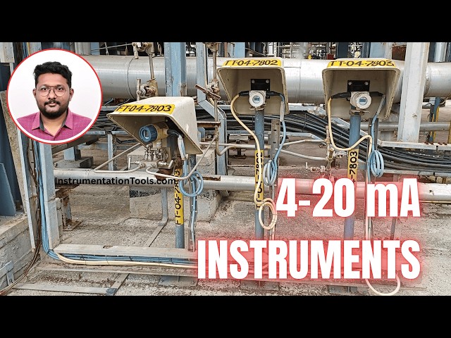
And in this picture we can see
2:14
uh temperature transmitters. See these
2:17
two are temperature transmitters. You
2:19
can see the tag name on the top. This is
2:23
the canop. TT means temperature
2:27
This is area code. This is transmitter
2:33
And this is the cable coming from the
2:37
And this is the cable going to the DCS
2:42
And this is one flow transmitter DP type
2:45
differential pressure based flow
2:49
All these instruments are 4 to 20 millia
2:54
based instruments. They support hot
2:56
protocol also for the configuration
3:00
of these instruments.
3:05
all instruments in the industries
3:09
operates on 4 to 20 millia basis
3:15
Every industry wherever you go you will
3:18
find 4 to 20 millia based instruments
3:24
and these are two wire instruments.
3:31
in this single cable? See this is the
3:34
single cable blue color cable. See
3:38
this is the blue color cable connected
3:45
provides power supply to the transmitter
3:50
and then carries this 4 to 20 millia
3:53
output to the DCS system using two wire
3:56
that means one pair cable.
4:01
You can see this is flow transmitter
4:04
only one cable is connected blue color
4:06
cable. This is a two wire instrument.
4:11
That is why it is very advantageous to
4:14
the installation cost optimization when
4:19
compared to three wire or four-wire
4:23
We have three-wire instruments.
4:25
Four-wire instruments also available
4:30
but majority the popular one is two wire
4:34
instrument. And next one is present
4:37
transmitters. Here we have three
4:39
pressure transmitters. See
4:43
back side we have a pipeline. On the
4:46
pipeline we have tapping point. See this
4:49
is the pipeline and we are measuring the
4:52
pressure inside this pipeline. For that
4:55
purpose there is a tapping point and
4:58
using impulse lines. Okay. These are the
5:05
This pressure is connected to the
5:07
instrument. Inside there is a pressure
5:12
and it calculates the pressure signal
5:15
and then transmitter sends this signal
5:17
to the DCS system using 4 to 20 milliamp
5:21
basis current signals. See all these
5:25
instruments hot protocol supported for
5:30
All instruments will be configured
5:33
uh using hot communicator as per the
5:37
design or as per the data sheet. And
5:41
this is a flow transmitter DP type.
5:44
If you see all these signals are carried
5:49
out using one pair cable.
5:53
We will call this cable as branch cable.
5:56
These cables will go to one junction box
5:59
installed in the field
6:02
and from the junction box one more cable
6:04
will go to the control room to carry the
6:09
I will show you the junction box also
6:12
for the 4 to 20 millia based signals.