Up next in 10

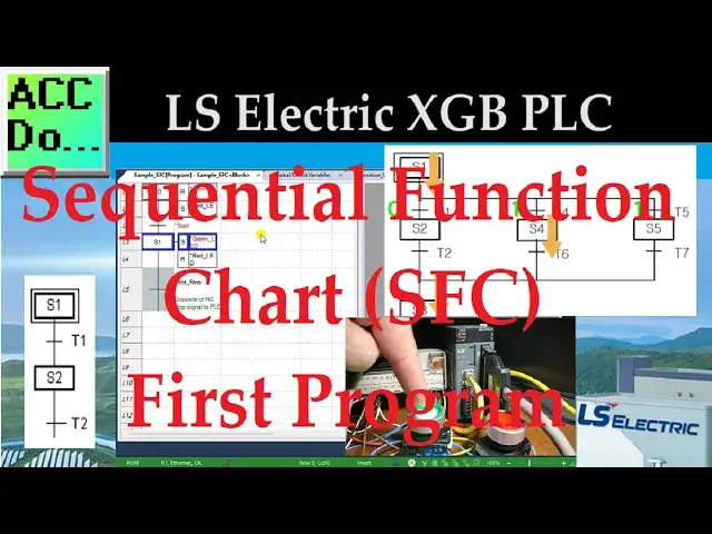
XGB PLC Sequential Function Chart (SFC) First Program
Nov 14, 2024
SFC (Sequential Function Chart) is a visual structured graphical language that utilizes PLC (Programmable Logic Controller) to organize application programs using flowcharts based on the processing order. SFC divides the application program into two main components: 'Steps' and 'Transitions,' providing a method to link them. Each 'Step' is associated with a specific 'Action', while each 'Transition' is connected to a 'Transition Condition.'
We will program our first Sequential Function Chart (SFC) in our LS Electric XGB PLC. SFC programming is commonly used in industries such as manufacturing, automotive, and process control, where complex sequences of operations need to be coordinated. It allows the programmer to visually organize the control logic, making it easier to design, understand, and maintain the control system (Troubleshooting.) SFC programming is beneficial for applications with many interrelated components and where the sequence of operations is critical to the system's overall functioning.
This post will explore the fundamentals of programming an XGB PLC using Sequential Function Chart programming. We will be programming our lighted pushbuttons to control a start-stop circuit. This will show the basics of this IEC programming language. Let's get started.
Detailed information and links can be found in the corresponding post here.
https://accautomation.ca/xgb-plc-sequential-function-chart-sfc-first/
The entire XGB PLC Learning Series can be found here:
https://accautomation.ca/series/ls-electric-xgb-plc-series/
00:00 XGB PLC Simulator Statement List (ST)
01:35 Start a New Project
02:48 SFC Command Summary
07:29 Create the Variable List
08:16 Create the SFC Program (XGB PLC)
12:29 Transfer the Program
13:43 Monitor / Modify the Program
LS Electric XGB PLC Series https://accautomation.ca/series/ls-electric-xgb-plc-series/
FAQ
Show More Show Less View Video Transcript
0:03
sfc sequential function chart is a
0:05
visual structured graphical language
0:07
that utilizes PLC or programmer logic
0:09
controller to organize application
0:11
programs using flowcharts based on the
0:13
processing order sfc divides the
0:16
application program into two main
0:18
components steps and transitions
0:21
providing a method to link in them each
0:24
step is associated with specific action
0:26
while each transition is connecting to
0:28
transition conditions we will program
0:30
our first sequential function chart sfc
0:32
in our LS electric xgb PLC sfc
0:36
programming is commonly used in
0:37
Industries such as manufacturing
0:39
automotive and process control where
0:41
complex sequences of operations need to
0:44
be coordinated it allows the programmer
0:46
to visually organize the control logic
0:48
making it easier to design understand
0:50
and maintain and the control system or
0:53
troubleshooting SSC programming is
0:55
beneficial for applications with many
0:57
interrelated components and where the
1:00
sequence of operations is critical to
1:01
the system's overall functioning this
1:04
post will explore the fundamentals of
1:06
programming an xgb PLC using the
1:08
sequential function chart
1:09
programming we will be programming our
1:11
lighted push buttons to control a start
1:13
stop circuit this will show the basics
1:16
of this IEC programming language let's
1:18
get started detailed information
1:21
contained in this video can be found at
1:22
ACC
1:28
automation.com video One it'll be links
1:31
to the rest of the videos in the series
1:32
as
1:35
well start a new
1:38
project run the xg5000 programming
1:41
software for the ls electric PLC
1:43
controllers under the main menu project
1:46
select new project this can also be
1:48
selected using the shortcut key
1:49
combination of Control Plus n there is
1:52
also a new project icon on the main
1:53
screen the new project window will now
1:56
be
1:57
displayed give the project a name the
2:00
directory where this program is to be
2:02
stored can also be set under the PLC
2:04
selection set the PLC that we will be
2:07
programming the CPU series is an xgb i
2:11
the type is an xm- dxxx H2 and we will
2:16
leave the default name of lslc under the
2:19
program heading we can name the sfc
2:22
program and select sfc program as the
2:24
programming
2:27
language a project description can also
2:29
be put into the new project window to
2:31
document what you are trying to
2:45
do select
2:49
okay sfc command
2:53
summary the new block program that we
2:55
named will now be displayed this is
2:57
where we will program our sequential
2:59
function chart code code under the main
3:01
menu edit tools a list of all sfc
3:03
instructions will be displayed this is
3:06
also shown on the top menu icons in the
3:08
corresponding shortcut
3:10
keys step
3:12
F3 in relation to action step functions
3:15
as a control unit for sequences where
3:18
each step is activated the corresponding
3:20
content of action is executed you must
3:23
first activate the initial
3:25
step transition a transition indicates
3:28
the conditions required for execution
3:30
between steps each transition condition
3:32
must be expressed using PLC language
3:35
either in structured text or latter
3:37
diagram the result of the transition
3:40
condition must always be of Boolean type
3:42
and the variable name should be trans
3:44
for
3:45
transition if the transition condition
3:48
evaluates the true one the current step
3:50
is deactivated the next step is
3:51
activated transitions are mandatory
3:54
between each
3:56
steps action F4 each step can can
4:00
contain up to two actions a step without
4:02
any action is considered a waiting
4:03
action which means it waits until the
4:05
next transition condition becomes true
4:07
or one an action is defined using PLC
4:10
languages such as latter diagram
4:12
sequential function chart or structure
4:14
text and the action executes while the
4:17
step is active an action qualifier is
4:20
used to control the action when the
4:22
action is deactivated after being
4:24
activated any output contacts activated
4:27
during the action will revert to zero
4:30
action
4:32
qualifier action qualifiers used
4:34
whenever an action is applied according
4:36
to the assign qualifier the action
4:39
related to the step defines an execution
4:41
point and the time the types of action
4:44
qualifiers are as follows n non stored
4:47
action is executed only when the step is
4:49
activated s set as the step is activated
4:53
the action is kept executing until the r
4:55
qualifier is executed r overwriting
5:00
reset it terminates executing an action
5:02
previously started by the S SD SL or DS
5:07
qualifier L time limited after the step
5:10
activation action is executed until the
5:13
step becomes inactive or until the time
5:15
set
5:16
elapses D time delay after the step
5:19
activation action is executed from the
5:21
moment the set time elapsed until the
5:23
step is
5:25
inactivated P pulse action is executed
5:28
only for the one scan when the step is
5:31
activated SD stored in time delay after
5:35
the step activation action is executed
5:37
from the moment the set time elapses
5:39
until the r qualifier is executed
5:42
however if the r qualifier is executed
5:44
before the elapse set time the action
5:46
does not
5:48
execute DS delayed and stored after the
5:51
step activation action is executed from
5:54
the moment the set time has elapsed
5:55
until the r qualifier is executed
5:58
however if the r qualifier is executed
6:00
or the step is inactive before the
6:02
elapse of the set time the action does
6:04
not
6:05
execute SL stored and time limited after
6:09
the step activation action is executed
6:12
until the set time has AAP or the r
6:14
qualifier is
6:17
executed block step F5 when the block
6:21
step is activated the specified sfc
6:23
sequential function chart program within
6:24
the block is executed only FFC programs
6:28
are permitted l D later diagram or St
6:31
structured text programs cannot be
6:32
included it is important to note that
6:34
actions cannot be linked to block steps
6:37
when the block step is deactivated the
6:39
sfc program running within the block is
6:41
also
6:42
deactivated label F6 labels can be
6:45
placed on your sequential function chart
6:47
depending on the sequence of operation
6:48
for your logic jump F7 the jump sfc
6:52
instruction can return to a label within
6:54
the
6:56
sequence left Branch f8 right Branch
7:01
F9 when the upper step is activated the
7:04
ne transition with a condition set to
7:06
one is activated among the multiple
7:08
connected transitions the executed
7:10
branch is the first transition activated
7:13
reading from left to
7:15
right in this example if the transition
7:18
condition of T4 and T5 is 1 the scan
7:21
order is S1 S4
7:24
S3 the processor chooses the leftmost
7:26
path
7:30
creating the variable list the first
7:32
thing to do is to create a variable list
7:34
we will use a program under the program
7:36
project window and the ls PLC double
7:39
click on the global direct variables
7:41
this will call up the global direct
7:43
variable window you can now enter the
7:45
physical inputs and outputs previously
7:47
wired to our LS electric xgb
7:50
PLC our sample sfc program will control
7:53
a start stop circuit when the start push
7:56
button is pressed the green LED light
7:58
will light up and the red LED light will
8:00
be off when the stop button is pressed
8:02
the red LED light will light up and the
8:04
green LED light will be off initially
8:08
the red LED will be on at the start of
8:10
this sfc
8:12
program save the
8:16
program create the sfc program xgb
8:21
PLC select the sample sfc program window
8:25
we can now create the sequential
8:26
function chart code all available
8:28
commands for the SF C are under the main
8:30
menu edit tools the shortcut function
8:33
code is also listed to the right of each
8:35
command there are also sfc command icons
8:39
on the main menu in the xg5000
8:41
programming software for your
8:43
convenience click the step command F3
8:45
and move your mouse to the sample sfc
8:47
program area click the spot where you'd
8:49
like to place the step and
8:51
transition the step is set for the
8:54
default of s0 double click on this step
8:56
will allow you to change the label we
8:58
will leave this as default
9:03
s0 click the action command
9:07
F4 select the s0o step for this action
9:11
the action property windows will be
9:12
displayed select the F to select the
9:15
green LED variable and select okay since
9:18
we you're not finished with this step
9:20
action select the arrow or escape from
9:22
the main menu icons double click on the
9:24
action for the step to recall the Action
9:26
Properties window again change the
9:29
quality ifier from n non stored to R
9:32
overriding
9:34
reset select
9:36
Okay click the action command once again
9:39
and select the previous action this will
9:41
again call up the Action Properties
9:43
window the default type is variable
9:46
select the F button and select the red
9:48
LED variable change the qualifier to S
9:51
set when the first step is executed the
9:53
green LED light will be off and the red
9:56
LED light will be on
9:59
the transition to the next step is shown
10:01
the bottom of the previous step double
10:02
click on the box next to the transition
10:04
this will display the transition
10:06
properties
10:07
window select the variable under the
10:09
type
10:11
heading select
10:13
find select the start variable to
10:16
transition to The Next
10:22
Step select the step command again and
10:25
click the transition from the previous
10:26
step this will place the next step S1
10:29
one after the
10:30
transition set the actions for this step
10:33
so the qualifier will set the green LED
10:36
and reset the red
10:42
[Music]
10:52
LED select the transition after step one
10:55
this will add the Boolean variable
10:57
non-stop for the transition condition
11:01
[Music]
11:14
our sfc program is now complete however
11:17
we need to define the latest non-stop
11:20
variable now so it will change when we
11:22
required right click on the scan program
11:25
under the add item menu select program
11:28
the program property window will now be
11:30
displayed name this program and ensure
11:32
the language is set for latter logic
11:41
LD we can now set the condition for the
11:44
non-stop contact so the sfc program will
11:46
transition back to Step
11:49
Zero since the stop push button is wired
11:52
normally closed and C we will use the
11:54
normally closed stop contact to turn on
11:57
the non-stop output
12:01
this is the end of our program save the
12:07
program to check the program select it
12:09
from the main menu view if we had an
12:12
error it would show up as an error
12:13
warning in the program check
12:16
dialogue if you're enjoying this video
12:18
please hit the like button below keeping
12:20
up with all the latest automation
12:22
Innovations can be difficult so hit the
12:24
Subscribe button remember to click the
12:25
Bell beside your subscription fact to
12:27
receive those notifications
12:31
transfer the
12:32
program select main menu online
12:35
connection settings this will call up
12:37
the connection settings window select
12:38
Network browsing and then expand the
12:40
ethernet option this will search your
12:42
network for the ls electric xgb
12:45
PLC click on the IP address found and
12:48
select
12:53
okay returning to the connection setting
12:55
Windows we can now select
12:57
connect the bottom of the X g5000
13:00
programming window will be read this
13:01
tells us we are communicating with our
13:03
xgb PLC which is in stop mode transfer
13:07
the SSC program to the xgb PLC by
13:09
selecting right from the main menu
13:11
online the right to PLC window will be
13:14
displayed we will leave all the settings
13:16
as their default and select
13:18
okay our program will now be transferred
13:20
to the PLC the right complete message
13:22
will be acknowledged by selecting okay
13:31
the PLC connection will then be stopped
13:33
which is the blue bar at the bottom of
13:34
the xg5000 programming software select
13:37
connect from the main menu online we
13:39
will once again be connected to the
13:43
PLC monitor modify the
13:47
program select the monitor icon on the
13:49
main menu this will show the status of
13:51
our program as it executes in the PC
13:54
select the Run icon on the main menu
13:56
select yes to verify that we want to
13:57
change to run mode the bar at the bottom
14:00
of the programming software is now green
14:02
indicating that we are communicating
14:03
with the PLC and it is running our
14:06
code operate the green and red push
14:08
buttons to verify the program's
14:10
operation the sequential function chart
14:12
sfc program illustrates the basic
14:14
control Logic for our start stop circuit
14:34
now let's modify the stop start circuit
14:36
select disconnect from the main menu
14:40
online double click on the action
14:42
property for the green LED in Step One
14:45
change the qualifier to L time
14:47
limited under the time change this to 10
14:51
seconds if the syntax error like time
14:54
format happens a warning message will be
14:55
displayed indicating the format
14:58
expected the xg5000 programming software
15:00
is very
15:04
intuitive select
15:06
okay save connect and transfer the
15:09
program again to the xgb plc
15:33
Monitor and test our new logic by
15:35
operating the push
15:44
buttons you will now see that the start
15:46
push button is pressed it will only be
15:48
on for 10 seconds or until the stop
15:50
button is
15:57
pressed let's modify the non-stop
15:59
condition in the ladder so that when the
16:01
green LED light turns off after 10
16:03
seconds and the transition is also
16:06
activated using online editing from the
16:08
lad logic code we can now add a trailing
16:11
Negative Edge trigger for the green LED
16:13
light in our parallel with the stop
16:15
button
16:43
once we finished our online modification
16:45
of ladder write the modified program to
16:47
the
16:50
PLC monitor the new program and watch
16:53
the operation the step ends when the
16:55
green light turns off after 10 seconds
16:58
or if the stop by is
17:01
pressed programming an xgb PLC using
17:04
sequential function chart sfc language
17:06
offers a powerful and flexible approach
17:08
to designing control Logic for
17:10
Industrial Automation
17:11
applications you can develop robust and
17:14
reliable programs for the xgb
17:17
plc's with continuous learning and
17:19
adaption to new technologies you can
17:21
leverage sfc program to create Innova
17:24
Industrial Automation and control system
17:26
Solutions the xg5000 programming
17:29
software allows you to troubleshoot with
17:30
visual cues and AIDS
17:33
quickly now that you know sfc
17:35
programming click here to learn more
17:37
about programming and structure text
17:40
XT click here to see all the available
17:42
information for the xgb PLC from LS
17:45
Electric
#Manufacturing
#Computers & Electronics
#Programming
#Programming
#Factory Automation
#Data Sheets & Electronics Reference
#C & C++