Up next in 10

Master online editing and fail-safe on the P1-M622-16DR. Step-by-step tutorial with real-world examples.
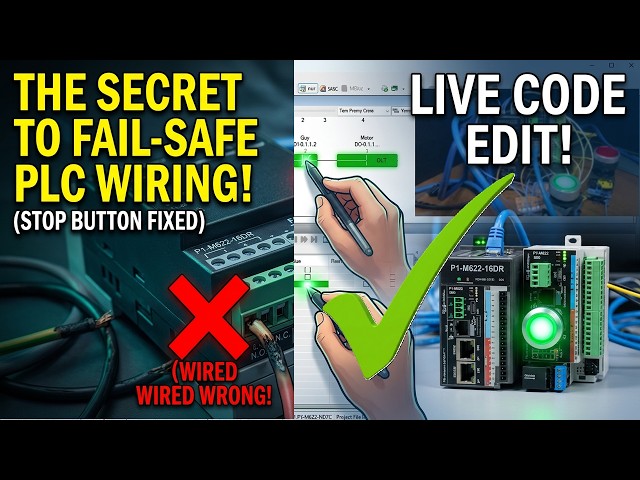
Discover why your stop circuits may not be fail-safe, and watch how to rewire and update your PLC program live—no downtime, just smarter safety!
📖 FULL WRITTEN TUTORIAL + DOWNLOADS
https://accautomation.ca/p1-m622-16dr-plc-learn-now-online-editing-and-fail-safe-wiring/
⏱️ TIMESTAMPS
0:00 - P1-M622-16DR Mini PLC - Learn Now Online Editing and Fail-Safe Wiring!
1:07 - Current Wiring Configuration Review
1:51 - Demonstrating the Problem – NOT Fail-Safe
3:06 - The Ladder Logic Problem
3:28 - Understanding Fail-Safe Wiring
4:43 - Rewiring the Stop Button
6:45 - Online Editing – Making the Change
8:44 - Testing the Fail-Safe Circuit
📚 WHAT YOU'LL LEARN
✅ P1-M622-16DR Mini PLC Online Editing and Fail-Safe Wiring! on the Productivity PLC
✅ Practical, hands-on approach
✅ Real-world tips from manufacturing experience
Show More Show Less View Video Transcript
0:03
The productivity suite software allows
0:05
us to modify our existing program and
0:07
execute the new code without stopping
0:09
the PLC scan.
0:12
This is referred to as online editing.
0:14
We change the latter logic code. And
0:16
when we save it to the PLC, the current
0:18
PLC scan is held until the new code is
0:20
written to the unit. It then releases
0:22
the scan and our new program begins
0:24
executing. This happens in milliseconds
0:26
so our process can continue to operate.
0:29
We're going to demonstrate something
0:30
critically important, failsafe wiring
0:32
for stop circuits. We'll show why our
0:34
current wiring configuration is not
0:36
failafe, rewire the stop button
0:38
properly, and then use online editing to
0:40
update our ladder logic to match, all
0:42
without stopping the PLC.
0:46
This is a lesson that could save
0:47
equipment, prevent injuries, or even
0:49
save lives in a real industrial
0:51
application.
0:53
Let's get started. Detailed information
0:55
contained in this video can be found at
0:57
accccclautomation.ca.
1:00
A link has been put in the description
1:01
below. The website offers extensive
1:03
links, references, and coding samples,
1:05
making it a one-stop shop for all your
1:07
automation queries. accutomation.ca.
1:11
Current wiring configuration review.
1:14
Let's review our current wiring setup.
1:16
Start push button DI01 1.1 wired
1:19
normally open N O. Stop push button
1:22
DI01.1.2.
1:24
two wired normally open N O lead light
1:26
motor DO01.1.1
1:29
represents the motor output. In our
1:31
latter logic, we're using a normally
1:33
open N O contact for start, a normally
1:35
closed NC contact for stop. An output
1:38
coil for the motor. The thinking behind
1:40
this design was the physical stop button
1:42
is normally open so when pressed it
1:44
sends a signal to the PLC. We use an NC
1:47
contact in the ladder so that when the
1:49
input turns on the contact opens and
1:51
breaks the circuit. This logic works
1:53
perfectly until something [music] goes
1:55
wrong. Demonstrating the problem not
1:57
fail safe.
2:00
Let's test what happens when we simulate
2:01
a wiring failure. This is the scenario
2:04
every control engineer needs to
2:05
understand. Step one, start the motor.
2:08
With the PLC in run mode, press the
2:10
start button. The motor output LED turns
2:13
on and seals in. Everything works as
2:16
expected. Step two, monitor the circuit.
2:18
Open the data view panel. Cautrol plus
2:20
shift plus F3. So you can see the status
2:22
of all our IO points. DI01.1.1
2:27
start off. DI01.112
2:29
stop off. D011.1
2:32
motor on. Also enable monitoring in the
2:35
ladder editor to see the logic flow.
2:38
Step three, simulate a wire failure. Now
2:40
with the motor running, carefully remove
2:42
one wire from the stop push button. This
2:44
simulates what happens if a wire breaks
2:47
due to vibration. A terminal connection
2:49
comes loose. A wire is accidentally cut.
2:52
Corrosion causes an open circuit.
2:59
What happens? Nothing. The motor keeps
3:01
running. Look at the data view.
3:03
DI0.1.1.2.
3:05
Stop is still off. In the latter logic,
3:08
the NC contact for stop remains true,
3:11
closed, [music] allowing power to flow
3:13
to the output. The critical problem. If
3:15
you try to press the stop button now,
3:17
nothing happens because the wire is
3:19
disconnected. You cannot stop the motor
3:22
using the stop button. In a real
3:23
industrial application, this could mean
3:25
an operator cannot stop a machine in an
3:27
emergency. Equipment damage continues
3:30
unchecked. Serious injury could occur.
3:32
This is not a failsafe design.
3:34
Understanding failsafe wiring.
3:38
A failsafe design means that when a
3:40
failure occurs, the system defaults to
3:41
the safe state. For stop circuits and
3:44
emergency stops, the safe state is
3:45
stopped. [music]
3:46
The rule stop buttons and emergency stop
3:49
estop buttons should always be wired as
3:51
normally closed and see contacts. Here's
3:54
why this works. Normally closed, stop
3:56
button wiring button not pressed.
3:58
Contact is closed. Current [music]
4:00
flows. Input sees 24 VDC.
4:04
Button pressed. Contact opens. Current
4:06
stops. Input sees 0 VDC off. Wire
4:08
brakes. Current stops. Input sees 0 VDC
4:10
off. Same as pressing stop. With NC
4:13
wiring, any failure in the stop circuit,
4:15
broken wire, loose connection, failed
4:17
switch, results in the same condition as
4:19
pressing the stop button, the machine
4:21
stops. This is a fail safe. Industry
4:23
standards. This [music] isn't just a
4:25
good idea. It's required by safety
4:27
standards, including FPA79, electrical
4:31
standard for industrial machinery, IEC
4:33
602041,
4:35
safety of machinery, OSHA regulations.
4:38
Emergency stop circuits have additional
4:40
requirements including direct acting
4:42
contacts and self-monitoring, but the
4:44
fundamental principle remains NC wiring
4:46
for stop functions.
4:49
Rewiring the stop button. Now, let's
4:52
make our wiring fail safe. Step one,
4:54
power down safely. Before making any
4:56
wiring changes, put the PLC in stop mode
4:58
or remove power. Never make wiring
5:01
changes with the system energized. Step
5:03
two, replace or rewire the stop button.
5:05
Change the stop push button from a
5:07
normally open N O contact to a normally
5:10
closed NC contact. Option A, replace the
5:13
button. If your stop button has N O
5:15
contacts, replace it with one that has
5:17
NC contacts. Most industrial stop
5:19
buttons are red and have NC contacts by
5:21
default. Option B, use the NC contact.
5:25
Many push buttons have both NO and NC
5:27
contact blocks. Simply move your wires
5:29
from the NO terminals to the NC
5:31
terminals. This is our case. New wiring.
5:34
One side of the NC contact connects to
5:36
24 VDC positive. The other side of the
5:39
NC contact connects to input 2D01
5:43
1.2. Input common C1 connects to 24 VDC
5:47
negative. Step three, verify the new
5:49
wiring. Power up the PLC. Keep it in
5:51
stop mode. Open data view and observe.
5:54
With the stop button not pressed,
5:55
DI01.1.2
5:57
should be on. Input sees 24 VDC through
6:00
the closed NC contact. Press the stop
6:02
button. DI0.1.1.2
6:05
should turn off NC contact opens. This
6:07
is the opposite behavior from before and
6:09
that's exactly what we want.
6:12
The ladder logic problem. Now we have a
6:15
problem. Our ladder logic uses a
6:17
normally closed NC contact for the stop
6:19
input. But with our new NC wiring, stop
6:22
not pressed, input is on, NC ladder
6:24
contact is false. Open motor can't run.
6:27
Stop pressed input is off. NC ladder
6:30
contact is true. closed. This is
6:33
backwards. We need to change the ladder
6:35
logic to use a normally open N O contact
6:37
for the stop input. This way, stop not
6:40
pressed. Input is on. N O ladder contact
6:43
is true. Closed. Motor can run. Stop
6:46
pressed. Input is off. No ladder contact
6:48
is false. Open. Motor stops.
6:52
Online editing. Making the change.
6:55
Here's where online editing becomes
6:56
valuable. We can make this change while
6:58
the PLC is running, minimizing downtime.
7:01
Step one, connect and go online. Make
7:03
sure you're connected to the P1M6216DR
7:06
via USBC or Ethernet. The PLC should be
7:08
in run mode with the CPU selector switch
7:10
set to run. Step two, locate the stop
7:13
contact in the ladder editor. Find the
7:15
NC contact for DI01.1.2
7:18
stop [music] in your start stop motor
7:20
rung. This will now be highlighted. Step
7:22
three, change the contact type. Locate
7:24
the N O contact under the contacts
7:26
instructions. Double click on the NO
7:29
contact. The replace instruction window
7:30
will now be shown. Select yes to replace
7:32
the normally closed NC with the normally
7:34
open N O. Step four. Notice the unsaved
7:37
indicators. You'll see symbols appear on
7:39
the left side of the modified rung
7:41
indicating that the program has been
7:43
changed but not saved or transferred to
7:45
the CPU. Step five, save the project.
7:48
Select file. Save project or click the
7:52
save icon. The symbols will change to
7:54
indicate the project is saved but not
7:56
yet transferred. Step six, transfer
7:59
using runtime transfer. Select file,
8:01
transfer [music] project to CPU or click
8:04
the transfer icon or press shift pulse
8:06
F9. The select transfer type window
8:09
appears. Select runtime transfer. This
8:11
option transfers the new program while
8:13
the PLC continues to run. Click okay to
8:16
begin the transfer. Step seven, verify
8:18
the transfer. The transfer project to
8:20
CPU window shows the transfer progress.
8:22
When complete, the ladder logic will
8:24
resume monitoring with the new code in
8:26
[music] effect. The entire transfer
8:28
happens in milliseconds. The PLC scan is
8:30
briefly held while the new code is
8:32
written. Then execution continues with
8:34
the updated program.
8:36
If you are enjoying this video, please
8:38
hit the like button below. Keeping up
8:40
with all the latest automation
8:41
innovations can be difficult, so hit the
8:43
subscribe button. Remember to hit the
8:45
bell next to your subscription to
8:47
receive notifications.
8:49
Testing the failsafe circuit.
8:52
Now let's verify our failsafe design
8:54
works correctly. Test one. Normal
8:56
operation. Press start. Motor turns on.
8:59
Release start. Motor stays on. Sealed.
9:01
Press stop. Motor turns off. Release
9:03
stop. Motor stays off. Test two. Fail
9:06
safe test. Press start. Motor turns on.
9:08
With the motor running, remove a wire
9:10
from the stop button. The motor should
9:12
immediately turn off. Why this works?
9:14
When you remove the wire, the input
9:16
loses its 24VDC signal and turns off. In
9:20
the latter logic, the no contact per
9:22
stop opens, becomes false, breaking the
9:24
circuit. the motor stops. This is a
9:27
failsafe operation. Any failure in the
9:29
stop circuit, broken wire, loose
9:31
terminal, or failed switch automatically
9:33
stops the motor. Test three. [music]
9:35
Compared to before, remember what
9:37
happened with the old normally open
9:38
wiring? The motor kept running when we
9:40
removed a wire. Now it stops. That's the
9:43
difference between a dangerous circuit
9:45
and a safe one. The rules to remember.
9:47
[music] Stop buttons and estops should
9:49
always be wired with NC contacts. When
9:51
using NC wired buttons, use normally
9:53
open contacts in the ladder logic. The
9:56
combination of NC wiring and a normally
9:58
open ladder contact ensures failsafe
10:00
operation. Test your failsafe circuits
10:02
by simulating wire failures. Online
10:04
editing benefits. Make changes without
10:06
stopping production. Test modifications
10:08
in real time. Minimize downtime during
10:10
troubleshooting. Quickly respond to
10:12
safety concerns. Next time we will look
10:14
at using the PLC simulator on the
10:16
Productivity Suite software.
10:19
The Productivity Mini PLC series from
10:21
Automation Direct and specifically the
10:24
P1 M62216DR [music]
10:26
is a compact powerhouse that packs
10:28
serious capability into a surprisingly
10:30
small footprint. To see our first ladder
10:33
logic, click here. Click here to build
10:35
digital twins of 3D virtual machinery,
10:37
test control logic, and learn automation
10:39
without expensive hardware using machine
10:41
simulator.
#Industrial Materials & Equipment
#Factory Automation