Up next in 10

SolidWorks Part Modeling Tutorial 02 | SolidWorks Tutorial | SolidWorks Part Modeling |
Aug 29, 2024
#SolidWorks #solidworksmodeling #solidworkstutorial
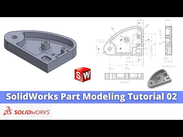
In this video I have explained How to Model Part in SolidWorks.
▶️ Download This Tutorial Source File From my Ko-Fi Store-:
https://ko-fi.com/s/d8a110f255
▶️ Visit my website for more info-:
https://mechnexus.com/
▶️ The Complete SolidWorks Course : From Zero to Expert!-:
https://www.udemy.com/course/solidworks-complete-course-zero-to-expert/?referralCode=B30458218EA1375DDB6E
▶️ Buy Me a Coffee
I am very grateful that you watch my videos and I am constantly trying to improve the quality of the videos on this channel. If you'd like to help me do this, please consider supporting me so that I can to continue to produce content for your enjoyment.
👉 Help support this channel by buying me a coffee: https://ko-fi.com/mechnexus
👉 Indian User can Support My Work Using my UPI ID: amar.patel456@ybl & amar.patel456@axl
All donations will be used to purchase equipment to improve my productivity and increase the quality of the content that I produce. Your kind support will help to grow this channel. Even if it's just enough to buy me a coffee every little helps and this will be repaid in full through my sharing of knowledge.
Show More Show Less View Video Transcript
0:01
Hello friends welcome to Solid Works
0:03
tutorial and in this tutorial we will
0:06
model this part which is a tutorial
0:08
number
0:08
02 and uh you can see that I have
0:12
successfully converted this orthographic
0:15
drawing into the 3D model and my 3D
0:18
model is also matching with a isometric
0:22
image so I will uh show you from the
0:26
scratch how you can model this part so I
0:29
will close this file and create a new
0:31
file you can also visit my website macn
0:35
nexus.com and you can visit this solid
0:39
works tutorials tab where I have written
0:43
so many tutorials on solid works where
0:46
you can follow the stepbystep guide to
0:50
model the
0:51
parts if you like my method of teaching
0:54
then you can also support me on kofi.com
0:57
you can buy me a cup of coffee
1:00
your small support will help these
1:03
channels to grow and it will motivate me
1:05
to create more awesome content on solid
1:08
works so let's come back to our
1:12
tutorial so here I have created a new
1:15
file and the first thing which I will do
1:17
is to select a top plane and uh we will
1:21
create this uh outer profile and uh then
1:25
we will extrude
1:27
it so the first thing which I will do is
1:32
to create a
1:36
rectangle and then here we will provide
1:40
the fillet of
1:42
31.75 so click on the fillet and give it
1:46
a
1:53
31.75 and here is a fillet of r25
2:00
[Applause]
2:04
and click on okay and now we will cancel
2:08
it and we will delete uh these two lines
2:12
and uh now we will uh join
2:17
it and
2:19
here we will uh add the
2:23
tangency and uh select and add the
2:28
tangent and now we will uh give the
2:30
dimensions so select smart
2:33
Dimension and provide this Dimension is
2:36
of uh
2:47
88 and this is the
2:50
[Applause]
2:54
140 here if you zoom the drawing it is a
2:59
140 and
3:01
uh this is the
3:05
88 and
3:08
now we will uh come out of the sketch
3:12
and uh I will provide this drawing in a
3:14
video description so you can check this
3:18
in a large view for the modeling I have
3:23
H split the
3:25
screen and uh here
3:29
we will close the sketch and uh we will
3:32
come out of
3:34
it and here uh we will extrude it to the
3:37
distance of
3:39
26 so click on
3:42
extrude and give it a distance of 26
3:46
click on
3:48
okay and now here uh we have missed one
3:53
thing which
3:55
is this radius so uh we will edit the
4:01
sketch and we will go to the front view
4:05
and we will delete this
4:07
line and uh create a 3point
4:12
Arc and uh this is of 180 so select
4:16
smart Dimension and give it a radius of
4:23
180 and
4:25
uh select uh this and this and uh add
4:29
the
4:30
tangency similarly select this and this
4:33
and add the
4:35
tangency and now we will come out of it
4:39
so as solid works is a parametric in
4:42
nature so our shape is got
4:46
updated now the next thing we will do we
4:50
will uh create this uh inner profile
4:54
and so we will select this pH and uh
4:58
click on the sketch and we will click on
5:01
the front
5:02
view and here some of the thing we will
5:07
convert it so we will select this this
5:10
and this and click on the convert
5:13
entities and we will select all and make
5:18
it for
5:21
construction and now press uh control 7
5:24
and now switch to the top view
5:31
and now we will uh create a three-point
5:34
AR here
5:37
select and create a three-point Arc and
5:42
here we will select this and this and
5:45
click on the
5:48
merge and then uh we will select a
5:51
three-point
5:54
Arc and we will again select a
5:56
three-point Arc and create Arc here
6:00
now similarly we will also merge the
6:03
center here click on the merge and this
6:08
and this uh will have the concentric
6:12
relation and this and this will have the
6:16
tangent
6:18
relation and now we will give the
6:23
dimension this is uh r25
6:30
and uh this and this having the
6:34
dimension 7
6:38
mm click on
6:41
okay and
6:44
here we will uh select a line tool and
6:48
uh we will uh create a rough profile
7:09
now we will select smart Dimension and
7:12
from this age to
7:14
this we will uh provide a dimension of 7
7:20
mm and from the age to this is of 45
7:30
this is of uh
7:35
25 you can check this Dimension uh with
7:38
the zoom of this
7:40
drawing and now I will uh give this
7:44
Dimension 13 mm
7:50
here and this is off 25
8:00
25 and uh from this
8:03
to this is of
8:07
[Applause]
8:11
25.5 and the from age it is 7 mm so we
8:15
will select this and this and provide
8:18
the 7
8:22
mm and this is off a 13 mm
8:26
so select it and it 13
8:31
mm so
8:36
here we will uh select this
8:40
line and this
8:43
line and this age and this is is having
8:46
the colinear relation so we will add the
8:48
colinear relation now our uh sketch is
8:52
fully constrained so we will come out of
8:55
it select the sketch click on EX R cut
9:00
and uh create a cut of 20
9:03
[Applause]
9:06
mm which we can see here and give the
9:10
value
9:12
20 click on
9:15
okay now here is a material so we will
9:20
select the ph and uh right click and
9:23
click on the sketch and uh make it
9:26
normal and uh create a
9:31
circle and select smart Dimension and uh
9:34
from the age it is of 70
9:40
MM 70 and
9:43
uh from the vertical it is of
9:48
63.5
9:51
63.5 and this is the diameter of 20 mm
10:02
and uh we will select the sketch and
10:06
click on
10:08
extrude select uh up to surface and
10:12
click on
10:15
okay and
10:17
now we will uh create this cut so for
10:20
this we will select this phase and uh
10:23
make this phase normal
10:28
[Applause]
10:30
and uh we will uh create a
10:36
rectangle and this rectangle ede having
10:39
the colinear relation with this ede so
10:41
we will select it and add the colinear
10:44
select this and this and add the
10:49
colinear select a smart Dimension and
10:53
provide this Dimension 17.5
10:59
and uh this is the horizontal dimension
11:02
of uh
11:05
24 now we will uh close
11:10
it and uh create a cut of 7
11:15
mm so select the sketch click on exude
11:19
cut and uh provide the depth of uh 7 mm
11:23
click on
11:26
okay and now we will create this hole so
11:30
for this we will select the face and
11:33
click on the sketch as uh it is a plain
11:35
drill hole so I am making with extrude
11:38
cut but it is recommended to use the
11:41
whole wizard
11:43
feature so snip to the edge so we can
11:46
get a center so we will create a
11:50
circle
11:52
and create
11:54
a diameter
11:58
13 click on
12:00
okay and exit and uh click on extrude
12:05
Cut and from here we will say it through
12:08
all say
12:10
okay and now we will uh create this hole
12:14
of uh di
12:18
10 which we can see in the projection
12:21
here of uh di 10 so we will select the
12:24
phase and click on the sketch and we
12:27
will make this phase normal select the
12:30
sketch and
12:32
uh create a circle select a smart
12:35
Dimension and view it of
12:39
uh 10
12:41
mm now we will uh come out of the
12:46
sketch and uh select extrude
12:51
cut and from here say it through all say
12:57
okay and now we will create this four
13:01
holes and this for four holes we will
13:04
select this phase and click on the
13:06
sketch and uh we will make it normal and
13:10
here first we will create a
13:16
rectangle and we will select all and
13:20
make it
13:21
construction and here we will draw these
13:24
four circles
13:36
and
13:37
now we will uh provide the diameter
13:40
which is of
13:46
6.5 and uh
13:49
then I will select uh all the circle by
13:54
pressing the control key
14:00
and uh
14:02
made this equal and now we will uh
14:07
positions so we will select smart
14:09
Dimension select this and this and
14:13
provide the value of
14:17
6.5 and uh horizontal dimension of uh
14:23
12.5
14:25
12.5 and Center to Center distance uh is
14:30
of
14:35
38
14:37
and from the
14:39
bottom it is of
14:47
38.5
14:48
now if you zoom here we can see these
14:52
Dimensions
14:53
here
14:55
now we will uh come out of the sketch
15:00
and create a hole so click on exclude
15:03
cut and uh say it through all say
15:10
okay and now here is a fillet of r f
15:15
which is a
15:17
typical so we will select this pH and
15:21
click on the
15:22
fillet and provide the value of
15:26
R5 and we will also select this pH
15:30
so you can see that it has given the
15:32
fillet now we will say
15:36
okay now we will again click on the
15:40
fillet and we provide the fillet to this
15:43
vertical
15:44
edges so select this
15:48
ede uh not face we want ages
16:00
and uh we will select this
16:05
one this and
16:10
this select this
16:13
Edge this
16:15
H so here is a tangency propagation
16:18
that's why it uh creating this fillets
16:22
at a bottom Edge as well and now we will
16:25
select this Edge and select here
16:30
and we will also select here the Four
16:33
Corners one
16:36
this one
16:38
this one
16:40
this and one
16:43
this now click on
16:46
okay now press contrl 7 for
16:50
isometric so this uh completes our model
16:54
and you can see that we have
16:56
successfully converted this uh
17:00
orthographic drawing into the 3D models
17:03
and if you go here and off the Shaded
17:06
view so we can see that it is a
17:08
perfectly matching with this uh
17:12
isometric view so this is all about this
17:15
tutorial and I hope you have enjoyed
17:18
this tutorial if you have enjoyed this
17:19
tutorial then please like subscribe and
17:21
share my channel and also support me on
17:24
a coffee.com you can buy me a cup of
17:26
coffee your small support will help this
17:29
channels to grow and it will motivate me
17:31
to create more awesome content on solid
17:34
works link is given in a video
17:38
description so this is all about this
17:40
part modeling tutorial thank you for
17:42
watching and thank you for your valuable
17:45
time