0:07
Hello everyone. Myself Bharadwaj. In the
0:11
previous video, we discussed about
0:16
In this video, I will discuss about
0:21
So, let's go back to the system cabinet.
0:25
Let's start from the field again.
0:28
From the junction box, one cable will go
0:31
from here to the marshalling cabinet,
0:34
right? So, this is our marshalling
0:37
cabinet. The cable entered here, the
0:39
trunk cable, and then it is connected to
0:42
surge protection device, and from surge
0:45
protection device, it will connect to
0:48
field bus power hub, and from the field
0:51
bus power hub, the interface cable or
0:55
prefab cable will go from here, and
0:59
again it will go to system cabinet, and
1:02
then it will connect to field bus card,
1:07
Right? So, this is marshalling cabinet.
1:11
So, now let us see the uh system
1:13
cabinet, how this interface cable is
1:15
going. I will show you the picture.
1:18
See, this is the interface cables
1:22
between system cabinet and marshalling
1:25
cabinet. We use these cables to connect
1:29
the marshalling cabinet and the
1:32
I/O modules in the system cabinet. We
1:36
have different types of I/O modules
1:40
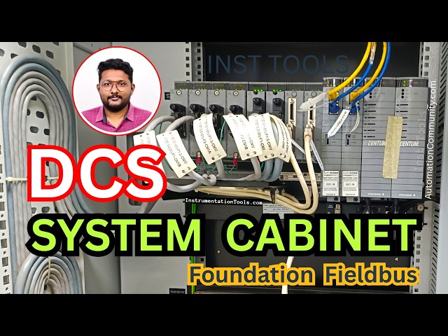
Now, let us see the system cabinet. So,
1:42
this is the system cabinet, where
1:45
the I/O modules, communication modules,
1:48
power supply units, CPUs are installed.
1:54
this is my system cabinet. See, these
1:56
are the interface cables coming from the
2:01
marshalling cabinet. Remember, we are
2:03
discussing with Yokogawa CENTUM VP DCS
2:08
So, this is a DCS system of Yokogawa.
2:15
See, these are the interface cables
2:16
coming from the marshalling cabinet,
2:19
right? And then, these cables will
2:23
connect to the respective
2:26
I/O modules. See, these cables connected
2:29
I/O modules. These are the I/O modules.
2:33
We have different types of I/O modules
2:36
available, like Foundation Fieldbus,
2:39
PROFIBUS, analog inputs, analog outputs,
2:43
digital inputs, digital outputs, RTD
2:46
module, thermocouple module,
2:49
communication module, Modbus, etc. So
2:54
The respective module will be installed
2:56
here, and the related cable will be
2:59
connected to the module.
3:01
The cable is coming from the marshalling
3:03
cabinet, and entered into the system
3:06
cabinet, and then connected to the
3:08
respective I/O module, right?
3:11
Now, I will show you the next one.
3:14
A little zoom, see? These are the
3:16
interface cables. See, these are dressed
3:18
like this properly, and then they are
3:26
This is Yokogawa DCS system.
3:31
Now, I will show you the another
3:33
picture. See, here it is very clear.
3:36
These are my cables coming from the
3:38
marshalling cabinet, right?
3:41
And this is the connector. This
3:44
connector is connected to the respective
3:47
These are the modules.
3:51
You can see the type of the module here,
3:53
the label is available.
3:55
This one is FF. The second one,
3:58
it is also FF. See, FF is written here.
4:01
This is FF. FF means Foundation
4:06
1 2 3 4 are Foundation Fieldbus related
4:09
cards. These two are analog input analog
4:13
output, that means this is a 16-channel
4:16
card, eight channel is analog input,
4:19
next eight channels are analog outputs,
4:21
combination of AI and AO.
4:24
This is also same. This is communication
4:29
And these two, the cables are connected
4:34
uh bus one and bus two. These two are
4:37
The processor cards of this FCS. And
4:40
these two are power supply cards.
4:44
So, these are the cards available in the
4:49
And see, the detailed labels are
4:52
mentioned here. The interface cable
4:54
connected to the respective I/O modules.
4:56
These are I/O modules from here to here.
4:59
And these two are communication between
5:02
the nodes. Node means this is one node,
5:07
Let's say you have multiple nodes.
5:10
Node one, node two, node three, node
5:14
So, we have CPUs installed only on node
5:17
one, the first line. See, these two are
5:20
In the next line, there are no CPUs.
5:23
In the next line, there are no CPUs. In
5:25
the next line, there are no CPUs.
5:28
So, the CPUs are only available in the
5:30
first line, that is a node one.
5:33
So that the node two, this is the node
5:35
two, the next one is node two,
5:37
related I/O modules data
5:40
will be transferred from here to the
5:42
node one CPU using these communication
5:46
cards, internal communication cards.
5:50
the node three, node four.
5:52
I'm not going in-depth about these
5:54
things here in this course.
5:57
So, I am restricting the topic now.
6:00
These field bus modules are there,
6:05
these modules act as link act to
6:10
in our network. We have two cables
6:13
coming from the field bus power hub in
6:15
the marshalling cabinet, right? In that
6:18
case, let's say these two are one set.
6:20
This one and this one, these two are one
6:23
Let us say the field bus power hub have
6:25
two cards. The first card is connected
6:27
here, the second card is connected here.
6:30
Like that, the two are
6:33
available next to each other, one left
6:37
In the two cards, only one card will be
6:40
active. The second card is standby.
6:43
You can see here on the top LEDs, uh the
6:46
in the labels are not clear, but I can
6:49
say that in the second card, we have
6:52
three lights, three LEDs. That means
6:54
this second card is in control. This is
6:59
Like that, and these two are one set.
7:01
That means these two are related to one
7:05
And in this, this is left card, this is
7:07
right card. In the left card, all three
7:10
LEDs are on, that means this card is
7:13
active, and the next card is in standby
7:17
Like that, by seeing the LED status, we
7:20
can identify the state.
7:22
Generally, if everything all right, then
7:25
the left card will be the in charge, the
7:27
second card is standby mode.
7:29
If anything happens to the active card
7:32
or communication network
7:34
due to any issue, then the control will
7:36
change from the left to right or right
7:42
Field bus cards will process the data
7:45
and provides this data to the CPUs.
7:48
These are the CPUs, processor units,
7:51
Then the processor units will receive
7:53
the data from the field bus cards,
7:56
and the processor cards then sends the
7:58
data to the operator workstations via
8:02
cables, bus one and bus two.
8:05
These are Vnet type cables or Ethernet
8:07
based cables for communication between
8:10
FCS, I mean controllers, and
8:16
So, this is related to Yokogawa DCS
8:21
These power supply modules provide two
8:23
types of power supplies. One is
8:26
5 V DC, and second one is 24 V DC.
8:31
In normal cases, the 5 V DC is for
8:33
operation of these electronic modules,
8:36
and the 24 V DC is for the field
8:40
But for Foundation Fieldbus, we are
8:42
providing another dedicated power supply
8:45
to the field bus power hubs, right?
8:47
Then the power take from the field bus
8:51
Uh this is FFTDU, fan failure and
8:54
temperature detection unit.
8:56
Uh cabinet related cooling fans will be
8:58
there, right? Yeah, this unit will take
9:01
care of those fans uh providing power
9:04
providing alerts to the users. You can
9:06
also set the temperature. Based on that,
9:11
So, this is about the brief
9:13
discussion about system cabinet
9:17
related to Foundation Fieldbus.
9:20
Remember, the system cabinet will be
9:22
common cabinet where all types of cards
9:25
will be installed. Let's say you have
9:27
Foundation Fieldbus, you have Modbus,
9:30
you have PROFIBUS, or any type of
9:32
communication, then all the cards will
9:35
be installed in this cabinet only.
9:38
So, as per your design, these cards will
9:40
be installed in the respective nodes and
9:45
So, this is all about the system
9:48
cabinet. If you have any questions
9:50
regarding the system cabinet,
9:53
please share with us,
9:56
thank you. Thank you for your support.