0:00
Hello friends welcome to Solid Works
0:02
tutorial and in this tutorial we will
0:04
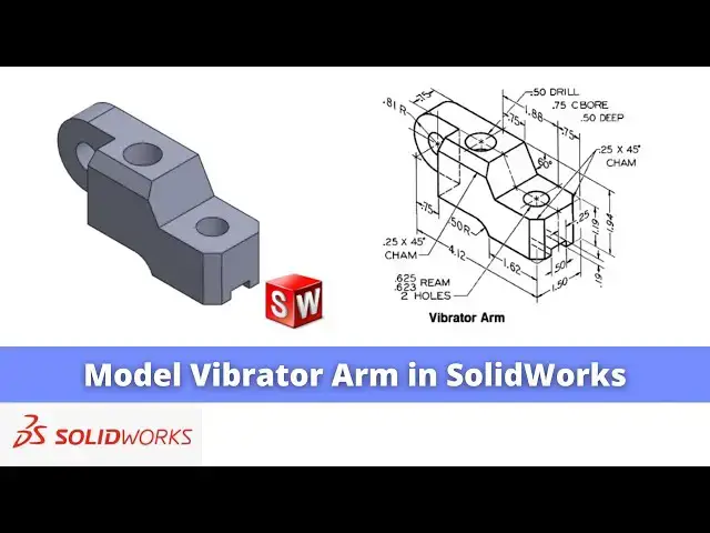
model this vibrator arm in solid works
0:07
as you can see that uh I have already
0:10
modeled it I will show you from the
0:12
scratch how you can model this vibrator
0:14
arm from the scratch so I will close
0:17
this file and create a new file you can
0:20
also visit my website macn nexus.com and
0:24
you can visit this solid works tutorials
0:27
tab where I have a written so many
0:30
tutorials on solid works where you can
0:33
follow the stepbystep guide to model the
0:38
parts if you like my method of teaching
0:41
then you can also support me on kofi.com
0:44
you can buy me a cup of coffee your
0:48
small support will help these channels
0:50
to grow and it will motivate me to
0:53
create more awesome content on solid
0:55
works so let's come back to our tutorial
1:01
so here I have created a new file and
1:04
first thing which we can see here this
1:06
dimensions are in inches so we will go
1:09
to the unit section and changes to the
1:13
second we will go to the setting option
1:16
and you can also change the unit from
1:19
here so you have both the option either
1:21
from here or from here so we have set
1:25
our units and if we see our parts then
1:29
we can see see that uh if we make our
1:32
first sketch on a front plane that would
1:36
easier so I will select the front plane
1:41
sketch and I will create this uh outer
1:45
boundary and then I will extrude it to
1:48
the 1.5 in so I will select the
1:57
line and I create a big Bic shape which
2:01
will be rough and then we will constrain
2:18
here we have created the basic shape so
2:37
and this radius here is A5 R in but
2:42
first we will constrain this it is a
2:49
1.62 and we will go to the fillet and
3:08
and give the0 five say okay and
3:14
now here we will delete this
3:23
and we will merge this
3:30
or we will delete this
3:35
fillet better to press the control
3:39
set so here we will not create the fet
3:43
first we will create a three-point
3:48
Arc and this 3point Arc will be tangent
3:54
this and it will be tangent to this
4:01
and we will select smart
4:08
it5 now we will use the trim
4:17
it and this will be 1.62
4:27
in and we will select this center line
4:30
or center point of this Arc and this
4:35
and at The Coincidence
4:39
constraint and now we can see here the
4:41
angle is 60 and this is the
4:46
1.19 so first we will
4:55
1.19 and this angle is of 60°
5:01
60 and from this point to this one is a
5:12
1.88 now we will uh close this sketch
5:18
uh here is our sketch is fully
5:20
constrained and now we will select the
5:22
sketch and click on extrude and give the
5:30
and select the mid plane click on
5:33
okay and now here we will give the
5:42
fillet select this and
5:57
okay now we will select the top face and
6:00
click on the sketch press control 7 and
6:12
rectangle and uh we will select this
6:18
age and give it value
6:26
and from this uh radius to this one is
6:37
75 and uh total length is uh doesn't
6:41
matter but we will uh keep outside of
6:46
body so we will switch to the top view
6:49
so it is of course outside of body now
6:53
we will come out of the
6:55
sketch select the sketch click on
7:00
and from here say true all say
7:05
okay now press uh control
7:08
7 and now we will create a cut here so
7:13
we will select the phase and click on
7:17
sketch and select the rectangle
7:23
tool and we will make this uh phase
7:29
and select smart dimensions and give it5
7:43
.19 and we will make this
7:46
symmetric so it will be 25
7:51
in so here is our sketch is fully
7:54
constrained we will come out of the
8:00
select the sketch click on extrude Cut
8:03
and from here say it through all say
8:10
now we will create this
8:15
hole select the phas and click on the
8:20
sketch make this phase normal click on
8:26
circle select smart Dimension and and uh
8:41
Cut say it through all say
8:45
okay because it is a two
8:51
here and uh this one and this one is the
8:55
same and this is of a 0.5 counter board
9:00
now we will give the chamfer of a025 to
9:05
this age so we will select the age and
9:07
go here and select the
9:19
okay and here also 025
9:38
now press the control 7 for isometric
9:41
View and now we will uh create this
9:45
counter board hole so we can see that it
9:47
is A5 drill so we will select the face
9:51
so first we will make the drill
9:54
hole select the circle and uh create a
9:58
circle and uh select smart Dimension and
10:01
from this H to this is a
10:08
75 and uh give the diameter.
10:18
and if you see here the whole Center in
10:20
a line with this Edge so we will make
10:26
normal and uh select this uh Center
10:31
Point and this Edge and add the
10:34
coincidence and come out of the
10:37
sketch and it is a drill hole so we will
10:40
select the hole and uh click on uh
10:44
extrude cut and from here we will say a
10:47
all so this is the drill hole and now it
10:50
is a 75 counter board with5 mm deep so
10:55
select the face and click on the sketch
10:59
and they will again make this phase
11:01
normal and create a circle to get the
11:06
center point snip the pencil on the edge
11:12
circle and here we will provide the
11:19
75 come out of the sketch and it is a 5
11:29
do the0 five and click on
11:39
okay now press the control 7 so as you
11:42
can see that we have a successfully
11:44
modeled this vibrator arm in solid works
11:48
and I hope you have enjoyed this
11:49
tutorial and if you have enjoyed it then
11:52
please like subscribe and share my
11:53
channel and also support me on
11:55
coffee.com you can buy me a cup of
11:58
coffee your small support will help
12:00
these channels to grow and it will
12:02
motivate me to create more awesome
12:04
content on solid works you can find the
12:07
link in a video description so this is
12:10
all about this tutorial of a vibrator
12:13
arm thank you for watching and thank you
12:15
for your valuable time