0:01
Hello friends welcome to Solid Works
0:03
tutorial and in this tutorial we will
0:05
learn extrude tool you can also visit my
0:09
website macn nexus.com and you can visit
0:13
this solid works tutorials tab where I
0:16
have written so many tutorials on solid
0:20
works where you can follow the
0:22
stepbystep guide to model the
0:26
parts if you like my method of teaching
0:29
then you can also support me on kofi.com
0:32
you can buy me a cup of coffee your
0:35
small support will help this channels to
0:38
grow and it will motivate me to create
0:41
more awesome content on solid works so
0:45
let's come back to our
0:47
tutorial this tool is inactive because
0:50
we have not created anything inside our
0:54
part so first we will select this top
0:57
plane and create a sketch
1:00
and I will simply select a
1:03
rectangle and I will uh draw a
1:08
rectangle and I give the dimensions
1:12
vertical select smart
1:17
Dimension you vertical
1:20
Dimension and before that I will change
1:28
mm and I give the the vertical height
1:40
horizontal I also give the 100
1:50
mm now we have a 100 by 100 square now I
1:55
will come out of the sketch
2:00
switch to the isometric view by pressing
2:06
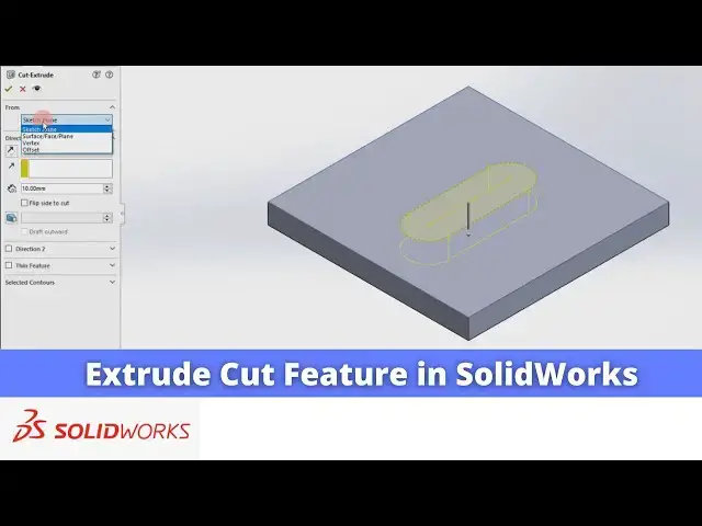
now extrude cut is a material removal
2:09
options so first we have to add the
2:12
material so let's click on the
2:16
extrude and here I will give the 10 mm
2:20
and I will say okay now I will select
2:23
this top face and click on the
2:27
sketch and I will select the slot
2:33
tool and I will select this centered
2:48
dimensions select smart Dimension select
2:53
age and give the dimension of 50 mm
3:02
horizontal and same select bottom ede
3:26
radius let's give the 10 mm
3:32
so we have the slot on this pH we will
3:38
sketch switch to the isometric View and
3:42
now we will select our sketch and click
3:48
cut so once we click on the extrude cut
3:51
we will have the multiple options as we
3:56
uh our extrude feature
4:01
now if we select the blind then we get a
4:04
arrow where we can drag
4:09
it whether we want through all Extrusion
4:13
or distance we want for example I wanted
4:22
okay so you can see that uh material is
4:25
remove of the 5mm from this top face
4:30
now if I click on exclude cut and edit
4:35
feature if I say through
4:38
all so it will completely remove the
4:49
okay now we again edit on a edit
4:56
feature next option is that uh up to
5:00
next up to Vertex or up to surface it is
5:04
a very simple plate when we will do the
5:06
part modeling then we will understand
5:08
this extrude cut features of up to next
5:14
surface and here is a one option is a
5:19
plane it will extrude to the both the
5:22
direction if I say 5mm then it will
5:25
exclude 5 mm top and 5 mm bottom side
5:30
but we do not have the material on the
5:32
top side so it will not cut on the top
5:38
okay so this is how it's
5:48
now we can also use the offset tool from
5:54
cut and uh offset from the surface these
5:59
are related to the parts when we will do
6:03
modeling and next one after the through
6:07
all is a through all on the both the
6:09
sides which means that uh you wanted to
6:12
remove the through all material on the
6:14
both the sides so if you click on it
6:17
then you will see the two Arrow one is a
6:20
top and other is a bottom as we do not
6:23
have a material on the top side so it
6:27
will not remove on the top side but
6:29
bottom side we have a material and if
6:31
you select okay then it will remove the
6:35
material so this is uh all about extrude
6:38
cut features in a solid works thank you
6:42
for watching and thank you for your