0:02
The ACC PLC simulator is a free
0:04
browserbased ladder logic editor and PLC
0:07
scan engine. There's nothing to download
0:09
and nothing to install. You open it in
0:11
Chrome, Edge, or Firefox, and you start
0:14
programming immediately.
0:16
I built this simulator so that anyone
0:18
learning PLC programming can get
0:19
hands-on practice without needing
0:21
hardware. Detailed information contained
0:24
in this video can be found at acccca.ca.
0:27
A link has been provided below. The
0:29
website offers extensive links,
0:31
references, and coding samples, making
0:33
it a one-stop shop for all your
0:34
automation queries. accautomation.ca.
0:42
When you open the simulator, you'll see
0:44
three main areas on the screen. On the
0:46
left is the instruction pallet. In the
0:48
center is the ladder logic editor, where
0:50
you build your program. And on the right
0:52
is the IO panel where you toggle inputs
1:01
The toolbar across the top gives you
1:03
access to run, stop, step, connect, and
1:06
other controls. Let's talk about the
1:07
toolbar. The run button starts the scan
1:09
engine. The simulator will continuously
1:11
scan your ladder logic, read inputs,
1:13
solve the logic, and update outputs.
1:16
This is the same as putting a real PLC
1:18
into run mode. The stop button halts the
1:20
scan engine, and the step button
1:21
executes a single scan cycle while in
1:23
stop mode. Step is one of the most
1:25
useful debugging tools in the simulator.
1:28
You can toggle an input, press step, and
1:30
see exactly what changed.
1:37
The instruction pallet on the left
1:38
contains all the instructions you can
1:40
use. For contacts, you have XIC, which
1:42
is a normally open contact that passes
1:44
power when the bit is true, and XIO,
1:47
which is a normally closed contact that
1:49
passes power when the bit is false. For
1:51
outputs, you have OTT, which is the
1:53
standard output coil, OTL, which latches
1:56
an output on, and OTU, which unlatches
1:58
it. The simulator also supports timers,
2:00
counters, and analog compare
2:08
The simulator uses standard PLC register
2:10
types. X registers are your digital
2:12
inputs. These represent physical devices
2:14
like buttons, switches, and sensors. A
2:17
registers are your digital outputs.
2:19
These control things like motors, pilot
2:21
lights, and solenoid valves. Creisters
2:24
are internal relays. They don't connect
2:26
to anything physical, but they are
2:28
essential for organizing complex
2:30
programs. The simulator also supports
2:32
timers, counters, and analog registers
2:34
for process control. The IO panel on the
2:37
right side of the screen is where you
2:38
interact with your program. Each input
2:41
has a toggle switch you can click to
2:42
turn it on or off. This is the same as
2:44
pressing a physical push button on a PLC
2:46
trainer. Outputs are readonly indicators
2:49
that show the current state as
2:50
determined by your ladder logic. Green
2:52
means the output is on. Analog inputs
2:55
have sliders that let you set a value
2:56
from 0 to 495, simulating a 12-bit
3:06
To build a program, click the add rung
3:08
button to create a new empty rung. Drag
3:10
a contact from the pallet onto the rung
3:12
and assign it a register address like
3:14
X1. Then drag a coil onto the right side
3:17
and assign it to a Y or C register. To
3:19
create parallel branches for O logic,
3:21
right click on a contact and add a
3:23
branch. Double click any element to
3:25
change its address or add a comment.
3:32
When you're ready to test, press run or
3:34
hit F5. Toggle inputs in the IO panel
3:36
and watch the ladder logic highlight in
3:38
green as power flows through true
3:40
contacts. The wires between elements
3:42
also turn green to show the power flow
3:44
path. This gives you an immediate visual
3:46
representation of how your logic is
3:48
executing in real time.
3:54
I recommend every beginner spend time
3:56
with step mode. It forces you to think
3:58
through the logic one scan at a time.
4:01
Put the simulator in stop mode. Toggle
4:04
the inputs you want to test. Press step.
4:06
Observe what changed. Which contacts
4:08
turned green? Which coils energized?
4:11
Then toggle another input and press step
4:13
again. This is exactly how you debug PLC
4:15
logic in the real world.
4:22
The simulator has a scene connection
4:24
system that links your ladder logic to
4:26
interactive 3D environments. Click
4:28
connect in the toolbar. Browse the
4:30
available scenes and click launch. The
4:31
scene opens in a new browser tab and
4:33
connects automatically. Once connected,
4:35
the 3D scene drives your X inputs and
4:37
your Y outputs drive the 3D objects.
4:40
There are five scenes available. The
4:42
control panel with start, stop, and jog
4:44
push buttons. The conveyor with
4:45
proximity sensors, the tank fill station
4:47
with float switches and a drain pump.
4:49
The traffic light intersection with
4:51
pedestrian buttons and the pick and
4:53
place palletizer with an XY gantry arm.
4:56
Two more scenes are in development, a
4:58
sorting bottle scene and a panel wiring
4:59
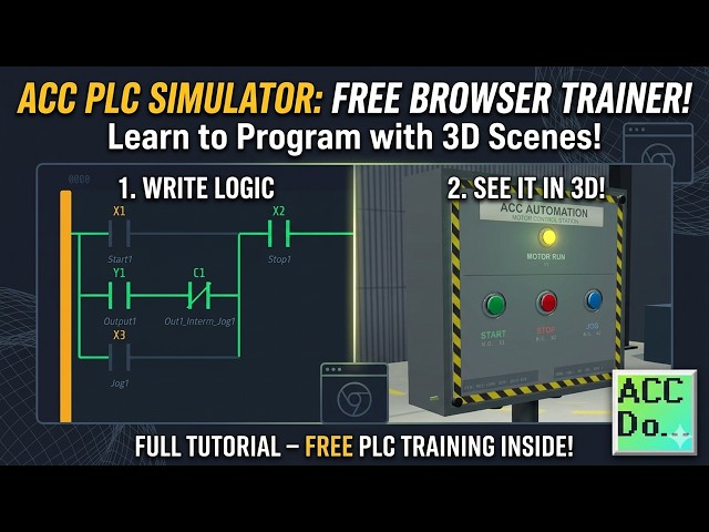
scene. The simulator comes preloaded
5:01
with a two-run start stop jog program.
5:04
This is a classic motor control circuit
5:06
that teaches three important concepts.
5:08
the seal in latch, which is how an
5:10
output holds itself on after a momentary
5:12
start button is released. The normally
5:14
closed stop, which shows why the stop
5:17
button is wired NC and what that means
5:19
for the XIC instruction, and the jog
5:22
interlock, which uses internal relay C1
5:24
to block the seal and path, so the motor
5:25
only runs while the jog button is held.
5:29
If you're enjoying this video, please
5:31
hit the like button below. Keeping up
5:32
with all the latest automation
5:34
innovations can be difficult, so hit the
5:36
subscribe button. Remember to hit the
5:38
bell beside your subscription to receive
5:45
Here are my tips for getting started.
5:48
Start simple. Build a single rung with
5:50
one contact and one coil. Run it. Toggle
5:52
the input. See the output respond. Then
5:55
add complexity. Use the step button.
5:58
Don't just watch things happen in run
5:59
mode. Stop the simulator. Toggle your
6:02
inputs manually and press step. This is
6:05
where the real learning happens. Use
6:07
internal relays. Creisters are your best
6:10
friend for organizing logic. And connect
6:12
a scene. The 3D scenes add a visual
6:16
layer that makes the logic much easier
6:21
accccclautomation.ca/simulator
6:23
to try the ACC PLC simulator yourself.
6:26
The link is in the description. If you
6:28
found this helpful, subscribe to
6:29
acccammation for more PLC tutorials and
6:32
leave a comment telling me what you'd
6:33
like to learn next. Thanks for watching.