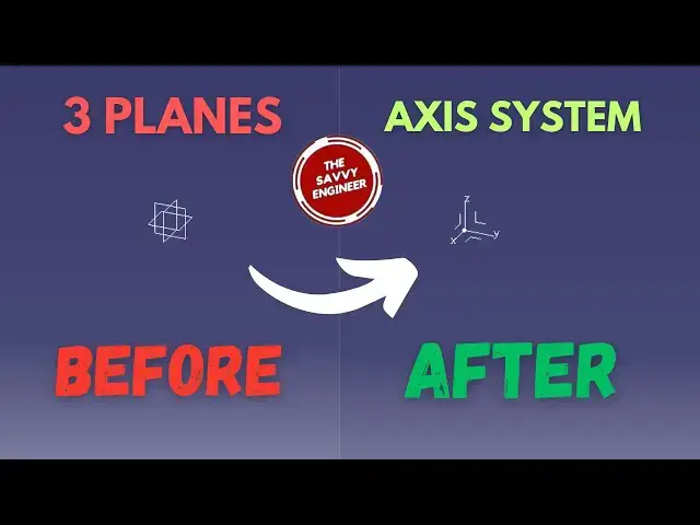
CATIA | How to Create an Axis System in 1 Minute!
Nov 7, 2025
Visit the Link Below to Learn More About How to Create an Axis System in CATIA like a Pro!
https://tinyurl.com/msk4xcma
--------------------------------
The Axis System in CATIA (typically referred to as the Current Axis System, or CAS) is perhaps the single most foundational element in any design. It's not just a visual reference; it's the mathematical anchor for every piece of geometry you create. Understanding why it's critical is key to moving from simple part design to complex, multi-component assemblies.
The Role of the CATIA Axis System
The Foundation of Parametric Modeling
CATIA is a parametric modeling software, meaning that all geometry is defined by relationships, not just absolute coordinates. The Axis System provides the origin (0,0,0) and the orientation (X, Y, and Z directions) that defines these relationships.
Sketches: Every sketch you create must reference a plane (XY, YZ, or ZX), and these planes are defined by the current axis. If your Axis System is wrong, your sketch orientation will be wrong.
Features: Features like holes, pads, pockets, and grooves are often defined by their distance or direction relative to the Axis System. If you move or redefine the Axis System, the geometry linked to it will update accordingly. This ensures design intent is maintained throughout the modeling process.
Assembly and Kinematics Alignment
When you move beyond a single part to build an assembly, the Axis System becomes a communication tool between components. Parts are constrained (mated) to each other using their local Axis Systems.
Imagine mating a flange to a pipe: you align the flange's Z-axis to the pipe's Z-axis and their origins. If these local Axis Systems are not consistently placed during the initial design of each part, the assembly will fail or require complex, time-consuming repositioning.
Show More Show Less #CAD & CAM
#Software
#Engineering & Technology
