live_tv
Livestream Starting Soon
00
Hours
:
00
Minutes
:
00
Seconds
Up next in 10

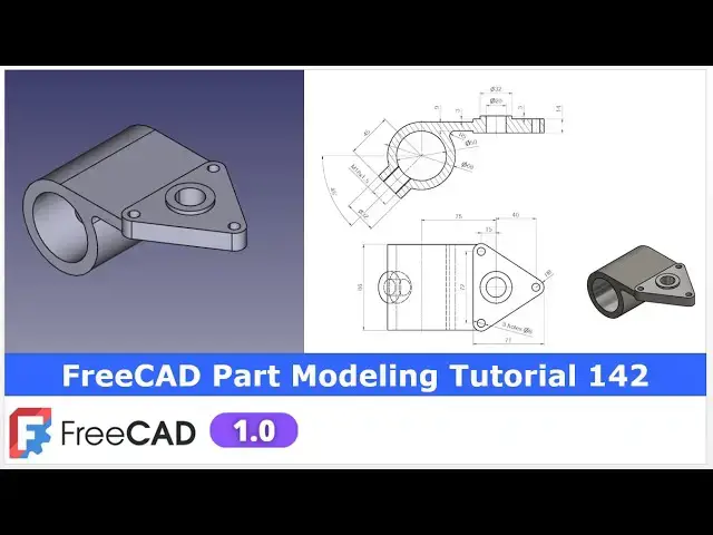
FreeCAD Part Modeling Tutorial 142 | FreeCAD Tutorial | 3D Modeling | Learn FreeCAD | Mechnexus |
Apr 24, 2025
#freecad #freecadtutorial #learnFreeAD
In this video I have explained How to Model Part in FreeCAD with the help of part design Workbench.
▶️ Join my channel membership and keep supporting my work:
https://www.youtube.com/channel/UCcn6z2whMaFu-_LDsEXCfVA/join
▶️ Visit my website for more info on FreeCAD-:
https://mechnexus.com/
▶️ Get my FreeCAD Crash Course for beginner-:
https://www.udemy.com/course/freecad-course-for-beginner/?referralCode=3BA9B526A12F96295D44
▶️ Download Source File of Tutorial-:
https://mechnexus.com/mechnexus-youtube-tutorial-source-file/
▶️ Buy Me a Coffee
I am very grateful that you watch my videos and I am constantly trying to improve the quality of the videos on this channel. If you'd like to help me do this, please consider supporting me so that I can to continue to produce content for your enjoyment.
👉 Help support this channel by buying me a coffee: https://ko-fi.com/mechnexus
Show More Show Less View Video Transcript
0:00
hello friends welcome to frea tutorial
0:02
and in this tutorial we will uh model
0:04
this part with respect to the our
0:07
drawing and uh you can see that I have
0:10
already model it and our frecad model is
0:13
matching with the isometric view we will
0:16
model this part from the
0:18
scratch for this tutorial i am using the
0:21
fread version 1.0 so you must have at
0:24
least 1.0 or higher version of a frecad
0:28
now I will uh close this file and we
0:30
will read the dimension of orthographic
0:32
view and we will create this uh model
0:35
which will match to the reference view
0:38
of our drawing so I will close this file
0:41
and create a new file you can also visit
0:44
my website
0:46
macexus.com where I write articles and
0:49
tutorials on a freecad and you can also
0:53
access my 3D part library of a free CAD
0:58
you can download the part from here and
1:01
you can use in your projects with
1:05
modifications
1:06
you can also access my 2D drawing
1:10
library where you can uh download this
1:14
2D drawings and uh you can create 3D
1:18
models with respect to these
1:22
drawings you can also support me on
1:26
coffi.com you can buy me a cup of coffee
1:30
your small support will uh help this
1:32
channels to grow and it will motivate me
1:36
to create more awesome content on uh
1:39
free cat you can find my Kofi donation
1:42
page link in a video description as well
1:46
as you can also see my Kofi page URL on
1:50
this
1:51
header so let's come back to our
1:54
tutorial
1:56
so here I have created a new file and I
1:58
will insert my body and I will on the
2:00
origin plane so as per the part
2:04
orientation we will uh create our first
2:07
sketch on a front
2:09
plane we will first create this profile
2:12
and then we will extrude it to the
2:14
symmetric with respect to the mid plane
2:17
so here I will select the exit plane and
2:20
click on the sketch i will off the
2:23
origin plane and select a circle tool
2:26
and create a two
2:31
circle and now I will zoom it inner one
2:35
is of 50
2:39
mm and uh outer one is of a
2:44
68 and let's move this dimension
2:50
and
2:51
now we will create a
2:54
rectangle so select a rectangle and
2:57
create a rectangle here and now I will
3:00
delete this vertical line and uh select
3:03
this point and axis and add a
3:06
coincidence select this
3:08
uh point and the arc and set the
3:12
coincidence now use the trim tool and uh
3:15
trim this and now let's uh constrain our
3:18
sketch so we will provide the horizontal
3:23
dimension which is of a 60
3:27
mm and uh thickness here is of a 9
3:32
mm so let's provide 9 mm our sketch is
3:36
fully constrained we will exist the
3:38
sketch and we will create a pad and in
3:42
pad we will uh
3:44
provide this is of 86
3:53
mm and here we will uh make it symmetric
3:58
to the plane and say okay
4:03
now the next feature is to we will
4:06
create this triangular pad on this face
4:09
so select the top face and click on the
4:11
sketch so now
4:14
here cube is got rotated so always check
4:17
the orientation press uh zero and uh
4:21
make this top view normal so we wanted
4:23
to create our
4:25
triangle on the face so our model it has
4:28
a right orientation i will select the
4:30
polyline tool and I will uh create a
4:36
triangle and now here we can see the
4:40
three
4:41
corners with a
4:45
fillet so we will select the fillet tool
4:48
and create a three
4:54
fillet and now we will make this all
4:57
three fillet equal which is of R8 so
5:00
select a smart dimension give this
5:03
fillet uh 8 mm and now select this this
5:09
radius and this radius and made it equal
5:12
and now let's give the
5:14
dimension so select a smart dimension
5:17
provide this to this is of uh 55 mm
5:24
select this
5:27
point and provide a
5:30
55 and constrain this point from this
5:33
point to the
5:35
origin is of a 60
5:39
mm and
5:43
now the hole to hole distance is of a 72
5:48
so we will use the symmetricity
5:50
constraint and we will make this point
5:54
and this point
5:57
symmetric so click on the symmetricity
6:01
select this point this point and this
6:03
axis and now select a smart
6:07
dimension and
6:09
uh provide the dimension of
6:12
uh
6:15
72 so our uh sketch is fully constrained
6:19
we will come out of the sketch and
6:24
now let's uh create this
6:27
pad so here if you see the upper side is
6:32
of 3 mm so we will create our extrusion
6:36
in a two
6:39
directions so let's create a pad and now
6:43
here we will select two dimension and
6:47
upper side we want 3 mm so give the here
6:51
3 mm and on uh other side we want 11
6:56
mm so you can see that
6:59
uh pad is created and you can cross
7:02
check this dimension
7:05
here say okay
7:09
now we will uh move to the next feature
7:13
which is to create a
7:16
pad press zero for isometric and select
7:19
this top face and uh click on the sketch
7:22
and press zero for isometric to check
7:25
the right orientation of a model so we
7:27
will create this on this axis so select
7:30
a circle tool and create a circle and uh
7:34
this is of
7:37
diameter 32 and the position is of
7:42
75 so if you go here so we can check it
7:46
is of
7:48
32 so first we will uh constrain the
7:51
diameter
7:52
32 and from center to center is of 75 so
7:58
we will switch to the top view select
8:00
this point and this point and uh provide
8:04
the 75 now click on
8:07
okay now we will uh create a pad and uh
8:11
this is the pad of 3
8:13
mm which we can see here so select the
8:17
sketch and click on the pad and give it
8:20
3 mm say
8:25
okay now if you see the section view so
8:30
there is a feature and which is a 45 mm
8:34
from the origin so we will create a
8:37
datam plane so we will on our origin
8:39
plane and here we will select this xy
8:42
plane and click on the datam plane and
8:46
if you see the front view so we will uh
8:49
rotate our plane to the 45° along the
8:52
yaxis so plane phase is selected and now
8:56
here on a y-axis I will provide a 45
9:00
mm so you can see that angle is created
9:03
at 45 and
9:06
now we will
9:08
rebuild our datam plane and off this
9:11
origin plane and now we will create a
9:15
plane at 45 mm
9:18
so click on the datam plane and uh
9:23
select this
9:24
plane and here provide the
9:28
distance of
9:31
45 so select the Z and here provide 45
9:36
mm so here it is going in other side so
9:40
change the sign from plus to minus and
9:43
say okay
9:46
now we need a axis at 45° so we will
9:50
press our model and on the origin plane
9:54
so here we will create one datim line
9:58
along the Z
10:00
axis so select the Z axis and now click
10:05
on the DATM line so you can see that uh
10:08
z axis is added here and here our
10:12
reference axis is y and along the yaxis
10:16
we will create a datm line at 45 so
10:20
under the around yaxis provide the 45 mm
10:23
so you can see that uh uh this
10:28
45° datm line is created and now we will
10:32
say
10:33
okay and let's rebuild our DATM line as
10:36
well and now let's uh off the origin
10:40
plane and uh we will select this offset
10:44
plane and uh create our sketch so now
10:49
the axis which we have
10:51
created we will project it so we will
10:54
click on the project geometry and we
10:56
will project it so this point is
10:58
projected here and
11:00
now it is basically the origin
11:04
point now I will uh create a circle and
11:09
select this
11:11
and origin point and add a
11:16
coincidence and here let's uh constrain
11:19
it which is of a diameter
11:23
32 select a smart
11:27
dimension and provide the diameter
11:30
32 and our sketch is fully constrained
11:32
we will come out of the
11:35
sketch now we will uh create a pad so
11:39
select the sketch and click on the
11:43
pad and from here select up to face and
11:46
define this
11:48
face and say okay and
11:53
now let's move to the next feature which
11:56
is to create
11:58
a hole on this face so select the face
12:02
and click on the sketch and now select
12:05
the circle and create a circle and uh
12:09
this is of a
12:11
diameter 18 because we have to give the
12:14
M18 thread so here I will uh give it a
12:19
18 mm and now I will close
12:22
it and now we will create the M18 tapped
12:28
hole so select the sketch click on the
12:31
whole
12:33
wizard and here select the isometric
12:37
regular
12:38
profile
12:43
and give the dimensions 30
12:47
mm and let's select the correct tap size
12:51
which is of
12:57
M18 and let's see it is opening
13:00
perfectly in this clearance area say
13:05
okay
13:07
now let's switch to the isometric view
13:10
so here we can see the cut so let's
13:14
place our model to the isometric select
13:16
the face and click on the sketch and uh
13:20
we will create a circle which is of a
13:23
diameter 20 so select the
13:27
circle and uh provide the 20
13:33
mm click on
13:36
close so here orientation got wrong so
13:39
let's edit the
13:42
sketch so
13:46
here let's delete this coincidence
13:50
constraint and move this circle click on
13:54
project geometry and project
13:56
it and then add a
14:02
coincidence this to
14:04
this
14:06
now let's create a cut so select the
14:09
sketch click on the
14:11
cut and uh set it through all and say
14:16
okay
14:20
now we will move to the next feature
14:23
which is to create these three holes
14:25
whose detail we can see here so these
14:28
three holes are the concentric with the
14:30
radius so we will
14:32
simply select the phase and click on the
14:35
sketch and this is of a three hole of a
14:38
dia 8 so let's press zero for right
14:42
orientation and uh click on project
14:44
geometry and uh project these three
14:47
radius now switch to the top view and
14:51
now here I will create a three
14:57
circle and let's constrain one of the
15:00
circle with a diameter
15:06
8 and now let's uh select all three
15:11
circle by pressing the control key and
15:13
made it equal so now I can make this
15:17
hole with the pocket tool but uh here I
15:19
will use the hole
15:21
wizard select the hole wizard tool and
15:24
here I will not select anything because
15:27
I want a simple drill hole provide the
15:30
diameter and from
15:32
here set it through wall and say okay
15:40
now if you see in a section view so
15:43
there is a radius of
15:45
R5 so we will select this H and uh click
15:49
on the
15:51
fillet and uh provide the fillet of 5 mm
15:55
say
15:58
okay press zero so you can see that we
16:02
have successfully modeled this part in
16:06
frecad with the help of a part design
16:08
workbench and our frecad model is
16:11
matching with a isometric view of a
16:14
reference
16:15
drawing so this is all about this
16:18
tutorial thank you for watching and
16:20
thank you for your valuable time
#Visual Art & Design
#CAD & CAM
#Sculpture