live_tv
Livestream Starting Soon
00
Hours
:
00
Minutes
:
00
Seconds
Up next in 10

#freecad #freecadtutorial #freecadpartdesign
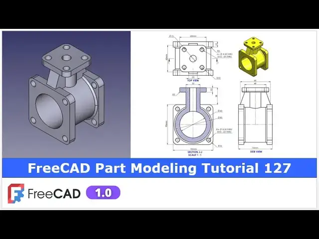
In this video I have explained How to Model Part in FreeCAD with the help of part design Workbench.
▶️ Visit my website for more info on FreeCAD-:
https://mechnexus.com/
▶️ Get my FreeCAD Crash Course for beginner-:
https://www.udemy.com/course/freecad-course-for-beginner/?referralCode=3BA9B526A12F96295D44
▶️ Download Source File of Tutorial-:
https://mechnexus.com/mechnexus-youtube-tutorial-source-file/
▶️ Buy Me a Coffee
I am very grateful that you watch my videos and I am constantly trying to improve the quality of the videos on this channel. If you'd like to help me do this, please consider supporting me so that I can to continue to produce content for your enjoyment.
👉 Help support this channel by buying me a coffee: https://ko-fi.com/mechnexus
All donations will be used to purchase equipment to improve my productivity and increase the quality of the content that I produce. Your kind support will help to grow this channel. Even if it's just enough to buy me a coffee every little helps and this will be repaid in full through my sharing of knowledge.
Show More Show Less View Video Transcript
0:01
hello friends welcome to free tutorial
0:03
and uh in this tutorial we will model
0:06
this part as you can see that uh I have
0:10
successfully converted this orthographic
0:13
drawing into the 3D model in frecad with
0:17
the help of a part design workbench and
0:19
you can see that uh our frecad parts
0:22
isometric view is matching with uh our
0:26
uh reference drawing i will show you
0:29
from the scratch how you can model this
0:32
part in freead so I will uh close this
0:36
file and create a new file you can also
0:39
visit my website macexus.com where I
0:42
write articles and tutorials on freead
0:46
you can download my tutorial source file
0:49
from here tutorial source file page and
0:52
you can also support me by buying a cup
0:56
of coffee on coffi.com your uh small
1:00
support will help this channels to grow
1:03
and it will motivate me to create more
1:06
awesome content on Frecad i thanks to
1:09
all my supporter those who have
1:12
supported me by buying a cup of coffee
1:16
so keep supporting and uh it will help
1:20
me to grow this channel and uh it will
1:23
motivate me to create more awesome and
1:26
useful tutorials on free so let's come
1:30
back to our
1:34
tutorial so here I have created a new
1:37
file and
1:39
uh for this tutorial I am using the free
1:43
version 1.0
1:45
so you must have a Frecad version 1.0 at
1:50
least or higher
1:52
version
1:54
now I will uh insert my body and I will
1:58
on my origin
2:00
plane
2:02
now we will uh create our first feature
2:05
on the front plane we will select the
2:07
front plane and click on the
2:11
sketch and uh I will off this origin
2:15
plane now we will draw this
2:20
uh in internal and external
2:25
diameter so click on the
2:31
circle and create a two circle
2:36
click on the smart
2:38
dimension and the outer diameter is of
2:41
80 and inner diameter is of
2:49
60 now we will uh come out of the
2:55
sketch and now we will extrude it to the
2:59
distance of 52
3:02
so select the sketch click on the pad
3:06
and uh
3:07
here tick mark symmetric to the plane
3:10
and give the distance
3:13
52 and say
3:17
okay now we will uh create this pad so
3:23
for this we will uh select this face and
3:25
uh click on the sketch and
3:29
here we will uh project this internal
3:33
diameter click on the project geometry
3:36
and project this diameter and
3:39
now create a
3:43
circle and uh press control key select
3:48
both and uh here you will see the option
3:51
of equal
3:53
constraint and
3:55
now click on the
3:58
rectangle create a
4:00
rectangle and now here we will uh make
4:03
it symmetric so click on the
4:06
symmetricity select this point this
4:09
point and origin
4:12
point press Ctrl Z
4:17
select this
4:18
point this point and origin
4:21
point
4:23
so
4:25
now we will give the
4:28
dimensions so select smart
4:31
dimension and uh it is a 90 mm now we
4:36
will uh press the control key and uh
4:39
select this uh vertical and horizontal
4:42
and uh make it equal so now our sketch
4:47
is fully constrained now we will extrude
4:50
it to the distance of 12
4:53
mm which you can see here so here I will
4:58
select the sketch click on the pad and
5:01
here I will give it uh 12 mm and say
5:05
okay now our uh next feature is to
5:10
mirror this pad on the other side so we
5:14
will uh select the pad 001 and click on
5:17
the mirror and we have the mid plane
5:20
here so we will go here and select
5:24
reference and we will select this mid
5:27
plane so you can see that uh it has been
5:30
successfully mirror on the other side
5:33
say okay now we will move to the next
5:38
feature so our uh next feature is to
5:42
create a DATM
5:47
plane to create a DATM plane we will uh
5:51
place our model to the isometric
5:55
view
5:57
and we wanted to create this top feature
6:03
so
6:04
here we will on our origin
6:08
plane and
6:11
here we will uh select
6:14
this XY plane
6:18
and here we will click on the create a
6:21
data plane option and here in a Z
6:26
directions give the dimension
6:29
83 you can
6:31
uh calculate this dimension from drawing
6:35
i have already calculated it so you can
6:38
see that a datim plane has been created
6:41
now I will off the origin plane and I
6:44
will
6:46
refresh my model now we will uh create
6:52
our next feature on this uh data plane
6:56
which will be this uh circular feature
6:59
so select the data plane and click on
7:02
the
7:03
sketch and here I will click on the
7:07
circle and
7:09
uh give the dimension of uh
7:15
32 click on
7:17
close and uh press the space bar and
7:21
hide this data plane now select the
7:25
sketch and click on the pad and uh click
7:29
on up to
7:33
face so you can see that feature has
7:36
been
7:38
created now say
7:42
okay now we have the solid face now we
7:45
will create this
7:48
uh pad square pad so select the face and
7:53
uh click on the
7:56
sketch and
7:58
now click on the twopoint rectangle and
8:02
uh create a
8:04
rectangle and now click on the
8:07
symmetricity select this point this
8:10
point and origin
8:12
point and here we can see the dimension
8:16
is of a 60 mm so select smart
8:22
dimension and give it
8:25
60 now press control key select this
8:29
horizontal and vertical and made it
8:33
equal and
8:36
now come out of the
8:39
sketch and we will create a pad of 10 mm
8:42
so select the sketch click on the
8:45
pad and uh
8:48
here we will uh reverse
8:51
it and say
8:55
okay
8:57
now our next feature is to create this
9:01
rib so we will select this bottom face
9:06
and uh click on the
9:08
sketch and we will uh switch to the
9:10
isometric view and we will rotate our
9:15
model and uh let's switch to the flat
9:18
lines and now here we will uh project
9:21
this
9:23
diameter to do that uh click on the
9:26
project geometry and project this
9:30
diameter and
9:32
now let's move to the bottom view and
9:37
here for the better sketching we will
9:40
switch to the
9:46
wireframe so that I can uh see now here
9:52
I will uh select a threepoint arc and uh
9:56
create one
9:58
arc and I will rotate it and I will
10:02
select this and this and made it
10:09
equal and I will select the center and
10:12
make it
10:14
coincidence
10:16
now we will select the line
10:19
tool and uh close our
10:26
profile now we will
10:29
uh give the
10:32
dimensions so we will keep this line
10:35
outside of a body but we will make it
10:41
symmetric so click on the symmetricity
10:45
select this point this point and this
10:49
axis
10:51
and give the dimensions
10:54
20 and from this line to this origin
10:58
point give it a approximate dimension 60
11:04
mm now let's see what is unconstrained
11:12
so here symmetricity is got removed
11:16
so we will again click on symmetricity
11:19
rather than this arc we will uh select
11:22
this point this point and this axis so
11:26
now you can see that our sketch is uh
11:29
fully constrained and now we will come
11:33
out of the sketch and uh we will also
11:37
switch to the flat lines view
11:42
and
11:43
now we will uh extrude
11:46
it so select it and uh click on extrude
11:52
let's give the approximate dimension of
11:54
60
11:57
mm now we will uh remove the extra
12:01
geometry in the next step
12:04
so first thing we will do is to mirror
12:08
on the other side because we can see the
12:11
same rib on the other sides so select
12:14
the pad click on the
12:16
mirror and from here click on select
12:20
reference and select this plane and
12:23
click on
12:25
okay
12:27
now we will uh remove the material the
12:32
dimension is given here so if you see so
12:36
this is the
12:39
48 so for that uh we will on our origin
12:43
plane and uh we will uh create our
12:47
sketch on this YZ plane and uh click on
12:50
the
12:51
sketch and
12:53
now from here we will switch to the
12:56
wireframe go to the model tab and of the
13:00
origin plane and
13:03
now we will uh click on the project
13:07
geometry we will project
13:11
it and
13:13
now select the line tool
13:18
and
13:19
here we can see that
13:23
uh this age is also required to be
13:27
projected so I will project it and
13:33
now I will uh select a line
13:37
tool and I will click on the project
13:40
geometry
13:42
again it is already projected here so I
13:46
will select this point and this line and
13:49
add a coincidence so this is the 48 so
13:53
from center this will be 24 so I will
13:57
select smart dimensions and from here to
14:00
here it will be
14:04
24 and uh this point is of
14:11
34 so give it uh
14:14
34 and
14:16
now we will close our profile and
14:20
completely remove the material so select
14:23
the line
14:24
tool select this and join it select this
14:28
and uh join
14:30
this select this and
14:38
join okay so we have the close
14:42
profile
14:44
now we will come out of the
14:47
sketch and from here we will uh switch
14:50
to the flat line select the sketch click
14:52
on the
14:55
cut and from here we will say it through
14:58
all and symmetric to the
15:01
plane so the material is removed
15:07
now we will mirror this pocket on the
15:10
other side so click on the
15:12
mirror and from here click on the select
15:15
reference and select the exit plane and
15:19
say
15:21
okay and now here I have not saved my
15:24
model so I will uh save
15:35
it
15:37
now let's uh moves to the next
15:41
feature which is to create this hole so
15:46
I will select this top face and click on
15:50
the sketch and this is the hole of a 15
15:53
mm which we can see here so click on the
15:57
circle and create a
16:00
circle and uh select a smart
16:04
dimension give it a 15 mm say okay and
16:10
now select the sketch and click on the
16:16
cut you can also use the whole
16:19
feature and now here I will give the
16:23
approximate distance of 56 mm so that uh
16:27
it
16:28
opens in a clear area
16:33
here say okay
16:38
now we will uh create these four
16:43
holes
16:46
and to do
16:49
that we will uh select the face and uh
16:53
create the sketch so if you see in a
16:57
model here in isometric view so this
16:59
hole is true and this is the size of
17:04
M10 so for that I will select this face
17:08
and click on the
17:10
sketch and here I will select a
17:14
rectangle and create a
17:17
rectangle and I will
17:21
uh select all the
17:23
sketch and make it
17:26
construction and at the same time I will
17:29
select this symmetricity select this
17:31
point this point and this uh
17:35
axis and select smart dimensions and
17:39
this is the
17:41
70 and
17:43
uh I will select this horizontal and
17:46
vertical and made it
17:49
equal and now here I wanted to create a
17:53
M10 hole so here I will create a four
17:58
circles
18:07
and select a smart
18:10
dimension give this 10
18:12
mm now press control key and select all
18:17
the
18:18
circles and give it
18:22
equal now we will use the whole wizard
18:25
tool so select the sketch
18:28
click on the whole
18:30
feature and from here select isometric
18:34
regular
18:35
profile and from here select the size of
18:40
M10 and I want this M10 hole on this
18:45
plate as well so I will make it through
18:48
all and say okay
18:53
now in the next step we will create the
18:56
hole on this top face which is also the
19:00
M10
19:02
size so we will select the face and
19:06
click on the sketch and here we will do
19:09
the same thing which we have did in our
19:12
previous steps so we will create a
19:14
rectangle
19:17
press the left mouse button and drag
19:21
it and everything is selected made it
19:24
construction now click on the
19:27
symmetricity select this this and origin
19:31
point and
19:34
now center to center distance 40 some of
19:38
the dimensions are missing in this
19:40
drawing so I have assumed some of the
19:43
dimension
19:45
so the dimension which are the missing
19:47
on the drawing follow the
19:50
video so here I will
19:53
uh give the 40 mm and now I will select
19:58
this and this and uh made it
20:02
equal now I will close
20:06
it here I will again edit the sketch and
20:09
I have not given
20:11
the whole diameter so as uh we have did
20:16
in a previous steps we will create a
20:19
four
20:20
circles constraint one of the circles
20:23
and made all four equal so here I will
20:28
make this 10 mm and press the control
20:33
key and select all four and made it
20:37
equal click on the
20:39
close and uh click on the whole
20:43
wizard and from here isometric regular
20:46
profile and uh set it
20:50
M10 and
20:53
here I have given the
20:57
dimension 25 but my plate thickness is
21:00
of a 10 mm so here I will give it a 10
21:05
mm
21:07
say
21:10
okay now press zero for isometric
21:18
view now we will uh create a fillet so
21:22
here is the fillet of 10 mm which we can
21:26
see here so we will click on the
21:32
fillet and
21:35
now we will select all the ages which we
21:39
wanted to give the fillet of uh
21:45
R10 i will select
21:49
this
21:56
this this
22:00
and this so here now I will give the
22:04
value of 10
22:07
mm and say
22:12
okay so you can see that fillet has been
22:15
created and now we will give the fillet
22:18
of
22:22
R3 to this
22:24
edge here and
22:29
uh
22:35
here and say
22:40
okay so now you can uh see that we have
22:45
uh successfully modeled this uh part
22:50
with respect to the orthographic drawing
22:53
now we will give the exact color as per
22:56
our isometric view so I will right click
23:00
my last feature go to the
23:02
appearances and here in a custom
23:05
appearances I will select uh this
23:08
diffuse color and select the
23:14
yellow click on close
23:17
so you can see that uh we have
23:20
successfully modeled this part in freead
23:24
this uh drawing and this isometric is
23:28
made in a solid work software but we can
23:32
see that freead is capable to create the
23:37
same type of a model i hope you have
23:42
uh enjoyed this tutorial so this is all
23:45
about this tutorial about the part
23:48
modeling and there are the some fillet
23:51
which are missing which you can provide
23:54
for example this R10 fillet is on the
23:59
top plate as well so to do that if you
24:02
miss any fillet then we will add in the
24:05
same fillet go to the edit and click on
24:10
the select and uh also select
24:14
this all four
24:25
edges and say
24:33
Okay now on the last feature so if if
24:39
you have missed any fillet then try to
24:42
give the fillet at once as we have seen
24:47
here we have given all R10 fillet in a
24:51
single fillet in fact you can do in a
24:54
two steps or a three step but my advice
24:57
is to not to increase the tree size keep
25:01
your tree size as much
25:04
as minimum possible from your end so
25:09
this is all about this tutorial thank
25:11
you for watching and thank you for your
25:13
valuable time
#Visual Art & Design
#CAD & CAM
#Sculpture