0:07
Hello everyone. Myself Bharadwaj.
0:11
In this video, I will discuss about loop
0:16
In one of the previous video, we already
0:19
discussed in this loop diagram for the
0:22
junction box and its wiring, right? Now,
0:26
in this video, I will discuss the
0:30
complete FF loop diagram from the field
0:34
to the control system.
0:37
We know that the junction box may have
0:40
some multiple number of field bus
0:42
barriers and instruments are connected
0:46
From one junction box, we receive one
0:51
from the field to the control system.
0:54
That means to the marshalling cabinet,
0:57
So, from the junction box to the
0:58
marshalling cabinet, we receive the
1:02
And from the marshalling cabinet,
1:05
again, the interface cable will come and
1:08
connect to the respective system cabinet
1:13
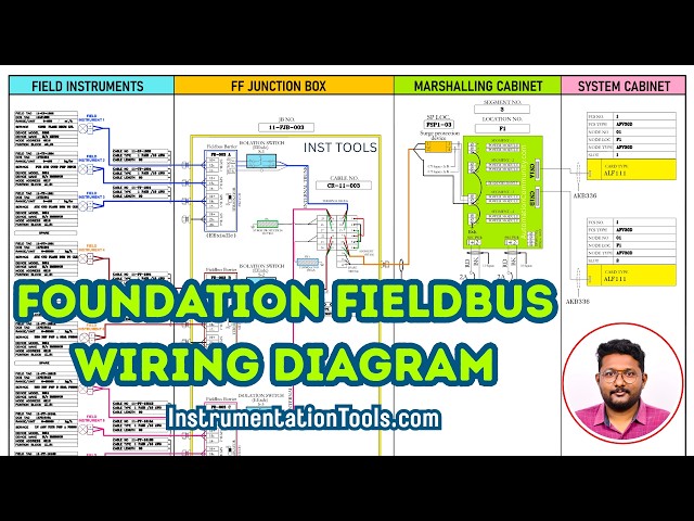
Now, let us see the loop diagram.
1:16
This is the complete loop diagram for FF
1:21
loop with three field barriers and one
1:27
Three field barriers means what? The
1:30
number of barriers inside the
1:35
From each junction box, irrespective of
1:38
the number of field bus barriers, we
1:41
receive one cable from the junction box
1:44
to the marshalling cabinet.
1:48
it is called as one segment. Each
1:51
junction box needs one segment in the
1:54
field bus power hub. If you see here, we
1:57
have different sections in this loop
2:02
field junction box location, marshalling
2:05
cabinet details, system cabinet details.
2:10
So, we know that in the field, we have
2:12
different number of field instruments
2:14
and those will be connected to the
2:19
Okay, this is the junction box inside.
2:21
Field bus barrier, isolation switch, and
2:26
This is field bus barrier A,
2:30
and C. We have three barriers here.
2:34
And each barrier have one dedicated
2:39
All these field bus barriers internal
2:41
trunks are connected in parallel using
2:44
this terminal block and jumpers.
2:49
Also, the trunk cable which is going to
2:51
the marshalling cabinet, that is also
2:53
connected in parallel.
2:55
And surge protection device, terminator
2:58
also connected in parallel using this
3:00
terminal block with jumpers.
3:03
Uh these are the field instruments
3:05
connected to the respective barriers in
3:09
From each junction box,
3:11
we will get one pair cable or two pair
3:14
cable. If you have a spare, then it is a
3:17
two pair cable. Generally, we have
3:19
spare, so we use only one pair. The
3:23
So, that is the orange color cable,
3:25
right? See, this is the
3:27
cable coming from the junction box so to
3:30
the marshalling cabinet, right?
3:33
This is the cable entered into the
3:38
In the marshalling cabinet,
3:40
it will go to the surge protection
3:41
device, right? So, this is the surge
3:43
protection device. This cable is
3:45
connected to the surge protection
3:47
device. And after the surge protection
3:49
device, it will go to the field bus
3:51
power hub. So, this green color module
3:54
is there, right? This is the field bus
3:56
power hub. In each field bus power hub,
3:59
we know that it has four segments.
4:03
Each segment supports one field bus
4:07
So, segment one, segment two, three, and
4:09
four. Each segment have two power supply
4:13
modules, the left and the right. Okay,
4:16
these are the modules.
4:17
And each field bus power hub have one
4:20
diagnostic module. So, this is the
4:24
This is the diagnostic module. You can
4:26
see here on the left side, these
4:28
terminals here, we can connect the cable
4:31
coming from the surge protection device.
4:34
This is for segment one, segment two,
4:36
segment three, and segment four.
4:39
If you see here, we have the plus,
4:44
The shield is common to
4:48
See, and connected to earth.
4:51
If you see here, this
4:54
field bus power hub, we have one primary
4:57
power supply and one secondary power
5:02
alarm feedback you can use.
5:05
And we know that each field bus power
5:07
hub have two connectors.
5:10
So, this is connector one and connector
5:15
First connector will be connected to one
5:17
dedicated field bus module. The second
5:20
one will be connected to second field
5:24
Now, with the help of interface cables,
5:26
these will be connected from the field
5:32
from the marshalling cabinet to the
5:36
See, this is a system cabinet.
5:38
And these are the panel numbers,
5:41
Okay, we are not going in-depth about
5:42
these numbers right now.
5:44
See, the connector one is connected to
5:47
and connector two is connected to this
5:51
You can get the details of your modules
5:53
here. Let's say this is the one module.
5:56
You can see the details of these two,
5:58
you can see node number one. Slot number
6:05
So, we'll go to the system cabinet.
6:07
If you see here, how many number of
6:11
Let's say this we call this one as node
6:16
This line, node three. And last one,
6:21
The lines means the way the cards are
6:26
So, the first one is node one.
6:29
These are all node one.
6:33
where is this card is installed?
6:36
Node one, slot one. This is the field
6:45
This is my node one, the first line. And
6:48
this is my slot one. This is the first
6:50
card from the left side. This is slot
6:53
This is slot two, three, four, five,
7:01
In this model, we have eight slots for
7:05
If you have multiple IO nodes, then the
7:07
first six will be used for the IO
7:09
modules. And the number seven and eight
7:12
will be used for internal communication
7:15
That depends on your model.
7:18
Now, it is clear that the first
7:20
connector is going to the node one, slot
7:25
What is the card model?
7:27
The model is AL F 111. This is the field
7:32
bus card model in Yokogawa DCS system.
7:37
Next, we'll see the connector two.
7:41
It is coming from marshalling cabinet
7:43
and it is going to the
7:46
system cabinet and the respective card
7:49
is installed in node one, slot two.
7:59
This is the first one is slot one, the
8:01
second one is slot two. So, these first
8:03
two cards are related to
8:09
this field bus power hub.
8:11
Remember, in Yokogawa DCS system, when
8:15
you are using a backup cards, redundant
8:18
cards, always the both cards are
8:20
installed side by side.
8:22
Okay, the left and right.
8:26
That is the Yokogawa's philosophy.
8:29
These are the power supply, primary and
8:31
secondary, 24 VDC from the bus bar.
8:36
So, that's it. This is the FF loop
8:41
Just overview the field instruments.
8:44
It is connected to the junction box.
8:46
From the junction box, one segment will
8:48
be connected to the field bus power hub.
8:51
From the field bus power hub,
8:53
again, it is connected to
8:55
field bus cards installed in system
8:59
Remember, it may have one barrier, two
9:01
barriers, three barriers. The concept is
9:05
In the next videos, I will show you the
9:07
detailed configuration and programming
9:12
Support us. Share our videos and