Up next in 10

Learn how to use the Reversible Shift Register (SFTR) instruction in OMRON PLC programming. Step-by-step tutorial with clear logic explanation and practical application.
JOIN OMRON FULL COURSE HERE:
https://learn.automationcommunity.com/courses/omron-plc-training-course-using-cx-programmer/
#OMRON #tutorial #programmingtutorial
Tags:
omron plc tutorial, sftr instruction omron, reversible shift register plc, omron sftr example, omron plc shift register, plc shift register tutorial, omron cx programmer tutorial, plc shift left right, sftr function in plc, omron plc programming, omron cx programmer sftr, plc shift register example, shift register omron plc, omron plc logic example, sftr instruction explained, reversible shift register cx programmer, omron ladder logic, omron plc training, plc register shift, plc logic design
Show More Show Less View Video Transcript
0:13
[Music]
0:17
hello everyone welcome to automation
0:19
community In this session we are going
0:21
to see about reversible shift register
0:23
in PLC Before entering into the topic
0:26
kindly like and subscribe our YouTube
0:28
channel for more updates and videos So
0:31
reversible shift register So what it is
0:35
going to do what is the function of this
0:36
this is having the additional features
0:38
of shift register So what are the
0:41
additional features let's see that in
0:43
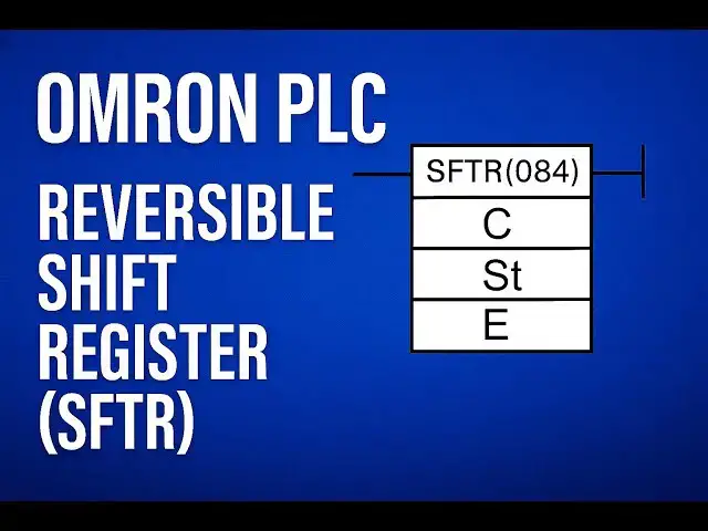
the in this video Okay So SFTR is the
0:47
short form for this instruction And here
0:50
we are having a control word starting
0:52
word and end address So this control
0:55
word is going to tell us what is the
0:58
data and which direction we are going to
1:00
do the shifting and when we are going to
1:03
do the reset and the input of shift when
1:08
when it have to be do the shifting
1:10
operation It depends upon that one bit
1:12
in this control word and here we are
1:14
having the starting word and here we are
1:16
having the ending word So the range
1:18
between the shifting operation in which
1:21
range we have to do this shifting
1:22
operation that details will be given by
1:25
this starting word and end
1:27
word So this is the control verb Here
1:30
you can see the last four bit of control
1:33
verb is going to tell us the details of
1:37
shifting operation The 12th bit is going
1:40
to tell us in which direction we have to
1:42
move whether it it have to be the right
1:44
or left And the 13th bit is the data
1:48
input So which data you want to do the
1:51
shifting that may be the one or zero
1:53
obviously So that will be
1:55
the data bit and 14th bit is the shift
2:00
input So if this is on shifting
2:03
operation will be happening If this is
2:05
off shift shifting operation will not be
2:07
happening And the 15th bit the last bit
2:10
is going to do the reset operation So
2:13
without any further delay we'll see this
2:15
instruction in the PLC program So
2:20
SFTR So let's see that in the
2:24
program Let's take one input
2:32
here
2:34
SDR I'm going to give some
2:37
address Okay
2:43
That's
2:44
it Okay So let's connect
2:49
this Let's take a watch window so that
2:54
we can able to see
2:56
the instructions working How it is
3:00
working so that you can able to see that
3:04
using this watch
3:07
window Okay Done
3:10
So let's take this
3:12
as you know rising
3:18
edge All right So let's go for the
3:34
simulation Okay Done So now let's give
3:39
some datas to this control word As I
3:43
have told you the last four bit is going
3:45
to give the datas I mean the instruction
3:49
like what it is exactly going to do
3:54
So let's I'm giving
3:56
six and some other value like okay now
4:01
see here this is 12th bit 13th bit 14th
4:05
bit and this is 15th bit so 15th bit is
4:09
zero so it will not do the reset
4:10
operation as of now All right And our
4:15
14th bit is one which is going to tell
4:17
us shifting has to happen or not Since
4:19
it is one it is giving the permission to
4:22
do the shifting
4:24
And 13th bit is one which is our data
4:27
bit Which data you want to move whether
4:29
it is a one or whether it is a zero So
4:32
now it is one So data is the one One is
4:34
the value which we are going to do the
4:36
shifting operation And the 12th bit is
4:39
zero That means the shifting is going to
4:41
happen towards the right direction Okay
4:46
So I'll give one pulse to the shift
4:49
instruction What is happening here is
4:52
from right side the data one is started
4:55
doing the shifting Can you see here one
4:58
here
5:00
okay So let's do one more
5:06
time Yeah So that one is shifted to the
5:10
up next bit and mu1 is coming to this
5:15
last place So since the end word is
5:18
having two 01 So what is 2011's you know
5:22
max uh in the last bit 15th bit All
5:25
right So since the shifting is towards
5:28
right it is starting from the address of
5:31
two not ones 15th bit towards the end of
5:36
starting bit which is our starting bit
5:40
200 200s 200 zero bit that means this
5:46
fellow it will move like this and it
5:49
will come towards like this Okay The
5:52
opposite of Z
5:54
See like
6:01
this So let's give one more pulse
6:10
See like that it will be
6:16
happening So for every pulse it is
6:20
moving or shifting one bit Okay Now what
6:25
will happen if I
6:27
add zero as the data data input So for
6:31
that we have to change here now and do
6:34
one thing So let's make the data to 4 1
6:40
0 So now look at this The shifting
6:43
direction is right only but the data is
6:46
zero now
6:47
Okay So now let's give a
6:51
input Look the data is zero No So it is
6:54
zero is adding here So now for every
6:57
pulse zero will be
7:00
adding
7:02
Look
7:04
Correct So like
7:07
that shifting operation is
7:11
happening Let's do one more stuff So
7:15
I'll make everything to 0 0 0 What does
7:17
that mean there is no shifting input So
7:22
if you give pulse it should not impact
7:24
our
7:29
data See nothing is happening because my
7:32
shift input is off Great So what it is
7:36
happening like
7:38
this So let's make to left shift So for
7:45
left shift I'm going to give the data
7:54
is so now it is
7:57
one Okay And uh this is my data but my
8:02
input is off So I have to give seven
8:07
here Yeah So my shift input is on data
8:11
input is one and uh you know shifting is
8:14
towards left So now let's give pulse
8:16
Let's see where that one is adding Look
8:20
so that you can understand
8:22
better Can you see here one is added in
8:26
the left most side So
8:29
D200's 200th address No in that zero bit
8:33
is the
8:34
leftmost Okay So for every pulse one is
8:38
adding towards the left side and data
8:40
will be moving towards this side So this
8:43
zero will get lost for the next pulse Up
8:45
next pulse this one will get lost Up
8:48
next this one will get lost So one will
8:50
be adding in these three
8:52
section Look at this
8:57
See So this is how reversible shifting
9:01
instruction will be working in Omron PLC
9:05
So what will happen if I add uh to
9:09
reset so to let's see
9:16
[Music]
9:18
that Okay So my reset input is on So if
9:23
I give pulse what will
9:24
[Music]
9:25
happen everything is zero That is what
9:29
reset is Now reset will do the complete
9:33
reset operation
9:35
So it will make everything to zero
9:36
between starting word and ending word
9:39
The data is completely zero So this is
9:42
how SFTPR reversible shift register will
9:46
be working in overall PLC I'll meet you
9:48
in the next session with another
9:49
interesting topic Kindly like and
9:52
subscribe our channel for more updates
9:54
and videos Thank you
9:57
[Music]
10:03
[Music]