Up next in 10

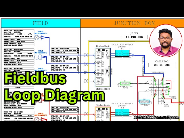
In this video, you will learn how to read a Foundation Fieldbus (FF) loop diagram used for field wiring. It explains trunk and spur connections, device addressing, segment structure, and how data is transmitted from field instruments to the control system.
👉 Get Full Fieldbus Course Here: https://learn.automationcommunity.com/courses/foundation-fieldbus-course/
✨ FOLLOW US ✨
👉WhatsApp: https://whatsapp.com/channel/0029VaAbUecLNSa4rDPOV31o
👉Telegram: https://t.me/+u3qORX5FKec1NjA1
👉LinkedIn: https://www.linkedin.com/company/instrumentationtools/
👉Facebook: https://www.facebook.com/instrumentationtoolss/
👉Instagram: https://www.instagram.com/instrumentationtools/
👉YouTube: https://youtube.com/instrumentationtools?sub_confirmation=1
👉JOIN Courses: https://automationcommunity.com/
#loopdiagram #fieldbus #fieldbustechnology
Tags:
foundation fieldbus loop diagram,FF loop diagram wiring,trunk and spur connections fieldbus,fieldbus segment layout,FF device addressing,fieldbus wiring explained,process automation loop diagram FF,field instrument wiring fieldbus,control system communication FF,junction box connections FF,segment topology fieldbus,industrial automation training FF,fieldbus cable routing,FF loop diagram interpretation,fieldbus course,fieldbus training,automation courses,courses
Show More Show Less View Video Transcript
0:07
Hello everyone myself Baradwas.
0:11
In the previous videos we discussed
0:14
about components of the junction box.
0:18
Right. In this video I will discuss
0:20
about this terminal block. see
0:26
these terminal block connections wiring
0:29
etc.
0:31
For that purpose I will use one loop
0:34
diagram of this junction box. This is a
0:38
junction box with three field barriers.
0:42
So I will open the
0:44
uh diagram.
0:47
See this is the diagram.
0:49
Here I am only showing the field and
0:52
junction box related wiring only. I am
0:55
not showing you the system related
0:58
wiring in this video but I will explain
1:01
it later. See the heading this is a FF
1:06
loop with three field barriers and one
1:10
segment.
1:11
So we know that this uh junction box
1:14
have three field barriers. It is clear
1:17
then what is one segment? See uh in FF
1:22
terminology
1:23
uh one main trunk cable is called as one
1:28
segment.
1:30
The cable going from the junction box to
1:32
the control room to the DCS system is
1:37
called as segment.
1:39
If one cable is going one segment, if
1:43
two cables are going two segments like
1:45
that. In general, each junction box have
1:49
one segment.
1:52
Okay.
1:54
And this is our
1:57
uh wiring diagram, loop diagram. If you
2:00
see here, this is our junction box.
2:03
Okay. This yellow color box. I added
2:06
some colors so it is easy to identify.
2:09
So this yellow color is the junction
2:12
box. In the junction box we have field
2:15
barrier. This is the field barrier one.
2:18
And each field barrier have one
2:21
dedicated isolation switch. So this is
2:23
our isolation switch.
2:27
And this is my second barrier field
2:30
barrier.
2:32
For this barrier we have one isolation
2:34
switch.
2:35
Similarly for the third field bus
2:38
barrier we have again
2:41
one isolation switch.
2:45
If you see here the first field barrier
2:48
sorry field bus barrier just consider
2:51
the field barrier as field bus barrier.
2:54
See in this field bus barrier we have uh
2:58
three instruments connected here. See
3:00
the uh blue color lines. This is my
3:02
instrument number one 2 3 and details
3:06
also available here. This is a LV level
3:09
control wall TT temperature transmitter.
3:12
Again TT temperature transmitter. So see
3:16
in field bus then we can connect any
3:18
type of instrument there is no
3:20
difference. Okay. So just consider as
3:24
instrument number one 2 three and the
3:26
fourth one is pair. See in the field bus
3:30
barrier if you see this is my spur one
3:32
that means instrument number one spur
3:35
two the cable is called a spur. This is
3:38
instrument number two three and four.
3:42
And this is terminator switch on and
3:44
off. And this is the trunk connection.
3:48
It will go to the isolation switch. From
3:50
the isolation switch it is going to the
3:52
terminal block.
3:54
In this trunk cable we have mainly two
3:58
terminals red, black, green. Okay, for
4:02
easy identification purpose I added
4:04
these colors positive, negative and
4:08
shield. Okay,
4:11
it is connected to 13 14 15. The first
4:15
field bus barrier. Next we will see the
4:18
second field bus barrier. This is my
4:22
second field bus barrier. In this field
4:25
bearer also we connected three
4:26
instruments. Instrument number four,
4:29
five, six. And this is pair.
4:34
Okay. And from the field bus barrier
4:36
will go to the isolation switch. And
4:39
from the isolation switch it will go to
4:41
the again terminal block where it is
4:44
connected this one 19 20 21 terminal
4:49
numbers.
4:51
Right? If you see here these three the
4:55
red color this one jumper the black
4:58
color jumper green color jumper these
5:01
are jumpers inserted inside the terminal
5:04
block. It may not be visible to you but
5:08
uh the jumpers are available there in
5:10
the function box. See 25 16 13 1 are
5:15
already internally connected. Okay.
5:17
Similarly 26 17 14 2 connected
5:22
internally 27 18 15 3 internally
5:26
connected that means this particular
5:29
horizontal line all internally connected
5:31
already clear. So this is my uh internal
5:36
trunk coming from the field bus barrier
5:38
one 13 and one are connected and using
5:42
this jumper external jumper
5:46
it is one and four are connected
5:49
again this complete line is connected
5:51
internally 22 1974 so the four is
5:55
connected to 19 7 22 so
6:00
I will consider this 4 and pin. This is
6:04
my see
6:07
uh brown color uh line coming from the
6:09
field bus barrier two.
6:12
In the field bus barrier we have
6:14
positive, negative and shield.
6:16
Uh the positive is 19. It is connected
6:19
to four. Again four is connected to one.
6:22
One is connected to 13.
6:24
Again uh the 20 negative it is connected
6:28
to five. The five is connected to two
6:31
using jumper because these are not
6:33
internally connected.
6:35
So two is connected to 14.
6:38
Similarly 21 6 and three. So if you only
6:43
see the uh trunks from the field bus
6:46
barrier 1 and two are a or b. See
6:52
19 13 connected
6:55
positive positive connected 201 14
6:58
connected negative negative connected
7:00
215 connected shield shield connected
7:04
that means these two are now in parallel
7:07
connection right here I only showing you
7:11
the external jumpers remember this is a
7:14
special TB all these horizontal lines
7:18
that means this complete Each row is
7:21
shorted internally.
7:23
Now we will go to the third field was
7:26
barrier. This is my third field was
7:29
barrier or barrier number C. A B C or 1
7:32
2 3 instrument 1 2 3 instruments are
7:34
connected and fourth one is pair.
7:38
Again field was barrier. It is going to
7:39
the isolation switch. From isolation
7:42
switch again it will go to the terminal
7:44
block. This is the cable. See it is
7:47
connected here. Right.
7:50
This pink color line is the field bus
7:52
number field bus barrier number three.
7:56
See the 16 is connected to 13, 17 is
7:59
connected to 14, 18 is connected to 15.
8:03
That means this is also in parallel.
8:06
Right?
8:09
So it is clear that the internal three
8:13
uh trunks each field bus barrier output
8:16
are in parallel. Okay. Now this is the
8:20
cable. The trunk going to the control
8:22
room. Let's see this is the trunk.
8:25
Trunk. Trunk. In the trunk we have one
8:28
pair cable we are using. And the second
8:31
one pair cable that is spare. See this
8:34
is the trunk. This is the spare 10
8:36
connected to 10 11 12. We are not using
8:39
this. Okay. Leave it. And in the first
8:42
one pair cable we are using. And that is
8:45
connected to 7 8 9. As already the
8:50
complete rows are shorted internally.
8:54
This trunk is connected to seven. The
8:56
positive one it is going to 19.
9:00
That means uh the third already three
9:03
trunks are connected in parallel. Now
9:05
the main trunk is connected to
9:08
um 19 or it is going to 7 to 4 4 to 1 1
9:13
to 13. Okay.
9:16
Again the negative to 8 8 to 5 5 to2 2
9:21
to 14 or 8 to 20.
9:25
Again shield 9 to 6 6 to 3 3 to 15 15 to
9:29
18 or 9 to 21.
9:33
See these are all contained in parallel.
9:35
Simple using uh jumpers, internal
9:39
jumpers and external jumpers.
9:42
Okay. Clear. Now it is clear that the
9:47
trunks it may be one number, two number,
9:50
three number all are connected in
9:52
parallel. Clear? Next
9:56
we'll go with the
9:59
s production device. This is also in
10:02
parallel.
10:03
See it has two terminals at okay. Uh and
10:09
it the main two terminals are going to
10:11
connected and 25 and 26. That means
10:15
already this these are all in parallel.
10:17
Now it is connected to 16 and 17. 16 is
10:21
positive. 17 is negative. Again s
10:24
protection device is also connected
10:26
parallelly.
10:28
Similarly check the terminator. This is
10:31
my terminator.
10:33
Again it is two wires are there for the
10:35
terminator
10:37
is connected 22 and 23. The 22 is the
10:40
positive side. 23 is the negative side.
10:44
So this s production device terminator
10:48
internal trunks uh outgoing trunk
10:51
everything is connected in parallel.
10:54
So this is my loop diagram. It is uh
10:57
showing you from up to field and
10:59
junction box it is showing and the
11:02
coming videos I will show you the
11:03
continuation of this part also. Now it
11:06
is clear that all trunks all main
11:09
instruments are connected in parallel.
11:12
Only this field bus barrier and
11:14
isolation switch are in series remaining
11:16
all are in parallel.
11:18
Now once again we will see this uh uh
11:21
internal junction box. This is my Okay.
11:26
This is my field bus barrier one. Uh
11:29
these are uh instruments coming from the
11:32
field devices or wiring coming from the
11:34
field devices. This is the internal
11:36
trunk. It is going to the isolation
11:39
switch. From the isolation switch, it is
11:41
connected here. See this is my first uh
11:46
trunk, internal trunk here.
11:50
This is the jumper. See the this one and
11:52
this one are jumpers. Okay, external
11:56
jumpers.
11:59
This is my second field bus barrier.
12:03
Instruments are connected here. Internal
12:05
trunk again. Isolation switch from the
12:07
isolation switch. This is the cable
12:10
cable cable cable control here. See this
12:13
is my second internal trunk. This is my
12:16
first internal trunk. If you see this
12:19
first two terminal, this terminal are in
12:21
line. This second terminal and this
12:24
second terminal are in line. So these
12:26
are connected. Okay.
12:28
And this is my third uh field bus
12:32
barrier. Instruments are connected here.
12:35
Uh internal trunk. It is going to the
12:38
isolation switch. Isolation switch to
12:40
the this is the cable going going going
12:43
here. Here. And this is my external
12:47
crunch. Uh outgoing crunch. See uh this
12:51
first one and this first one in line.
12:54
Second one. Second one mean second one.
12:56
Second wire. Okay. In line using uh
13:00
jumpers. This positive this positive
13:02
connected this positive. This negative
13:04
this negative is connected.
13:07
Okay.
13:09
Similarly uh terminator if you see here
13:13
two wires are coming red and black.
13:16
going connected in the uh terminal
13:20
block. Similarly, such protection device
13:24
three are there. Okay.
13:27
Red and black connected here in the
13:30
terminal block. All these are connected
13:33
in parallel for FF communication. These
13:36
are all connected in parallel. Finally
13:40
uh finally only two wires. That means
13:42
one pair cable will go from this
13:44
junction box to the control room to the
13:47
DCS system irrespective of the number of
13:50
field barriers, number of field
13:52
instruments connected to one junction
13:54
box. This one trunk cable going to the
13:58
control room is called as segment.
14:01
Segment one, segment two, segment three
14:03
like that. Remember you see these are my
14:07
each uh field bus barrier have four
14:10
spurs uh four instruments we can connect
14:12
and you can see the PWR power supply
14:16
status of this field bus barrier. You
14:19
can see the status green means healthy
14:21
and here if you see 1 2 3 4 1 2 3 4
14:26
these are LEDs.
14:28
We can see the healthiness status of
14:30
each individual instrument connected to
14:33
this particular field bus barrier.
14:35
Similarly, every field bus barrier have
14:40
LED status indications available on the
14:43
PCB and one terminate onoff switch is
14:47
also available. It must be non-state
14:49
then only this particular field bus
14:52
related instruments will be online
14:55
otherwise they will not work. Thank you.
14:58
I will meet you in the next video.
15:00
Meanwhile, please share and uh like our
15:04
courses and videos. Subscribe to our
15:06
channel. Thank you.