0:05
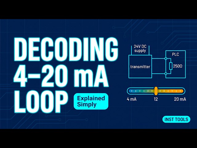
In industrial automation, the 4 to 20 mA
0:08
current loop is standard for a specific
0:10
reason. Even though 4 mA is the lowest
0:13
signal sent, it doesn't mean the loop is
0:15
off. That 4 mA baseline represents 0% of
0:19
the measurement. This creates a safety
0:21
gap. If a wire breaks, the current
0:23
immediately drops to 0 mA. Because the
0:26
control system is programmed to expect a
0:28
minimum of 4, it can instantly between a
0:31
zero measurement and a total system
0:33
fault. This is the live zero. This
0:36
diagram shows the mathematical baseline.
0:39
The bottom boundary is pinned at 4 mA,
0:41
representing 0%, and the top boundary is
0:44
20 mA, representing 100%. That means the
0:48
actual usable measuring space between
0:50
the floor and ceiling is exactly 16 mA.
0:54
Every calculation used to scale these
0:55
sensors relies on recognizing the
0:57
difference between that 16 mA span and
1:00
the 4 mA starting offset. To see how
1:02
this works in practice, imagine a flow
1:05
transmitter with a lower limit of zero
1:07
and a maximum capacity of 2,500 cubic
1:11
If the pipe is currently moving 1,500
1:13
cubic meters, we need to find the
1:15
equivalent mA output. The first step is
1:17
simple. Find the percentage of the scale
1:19
being used. 1,500 divided by the 2,500
1:23
capacity tells us the system is running
1:25
at 60%. Many engineering manuals suggest
1:28
using a formula like this. Take the
1:30
percentage, add 25, then divide by 6.25
1:33
to get 13.6 mA. Ignore the magic numbers
1:37
like 6.25 and rely on the physical logic
1:40
of the loop instead. Since we are at 60%
1:42
of the flow, we should be at 60% of our
1:45
usable signal. We take 60% of that 16 mA
1:48
span we identified earlier, which gives
1:50
us 9.6 mA. Now, just add the 4 mA live
1:54
zero offset back in. 9.6 + 4 gives us
1:57
the correct output of 13.6 mA.
2:00
By focusing on the 16 mA span rather
2:04
than the 20 mA ceiling, you avoid the
2:07
most common error in sensor scaling,
2:09
forgetting that the first 4 mA don't
2:12
count toward the measurement. When
2:14
you're troubleshooting in the field with
2:15
a multimeter, you'll want a single step
2:18
version of this calculation to check
2:19
your work. This is the field check
2:22
formula. You take your process reading,
2:24
divide by the max scale, multiply by the
2:27
16 mA span, and add the 4 mA cuz that's
2:30
directly to the same 13.6 mA result.
2:34
Let's apply this logic to a different
2:36
scenario. We have a storage tank with a
2:38
maximum capacity of 177,000
2:41
lb. This time, you're looking at the raw
2:44
signal. Your multimeter shows exactly 12
2:47
mA. Based on that 12 mA reading, what is
2:50
the current weight in the tank? Pause
2:53
the video here and try to work the logic
2:55
in reverse. Working the math backward is
2:57
how you troubleshoot a sensor that isn't
2:59
responding correctly. It allows you to
3:01
move from reading a screen to diagnosing
3:03
the physical loop itself.
3:05
Start by stripping away the 4 mA offset.
3:09
12 - 4 leaves 8 mA of usable signal.
3:13
Divide by the 16 mA span to find your
3:15
position. 8 / 16 is 50%. Multiply by the
3:22
lb capacity, and the tank holds 88,500
3:26
Whether you are converting a process
3:28
value to mA or mA back to engineering
3:31
units, the rule is consistent. Always
3:34
subtract or add the four, and always
3:36
scale using the 16. This cheat sheet
3:39
contains both versions of the formula.
3:41
You can screenshot this for reference
3:43
next time you're verifying a sensor in
3:44
the field. Once the relationship between
3:47
the 16 mA span and the 4 mA offset is
3:50
internalized, any standard current loop
3:52
becomes readable, regardless of the
3:54
units or the environment you're working