0:00
Today in this video we are going to draw
0:03
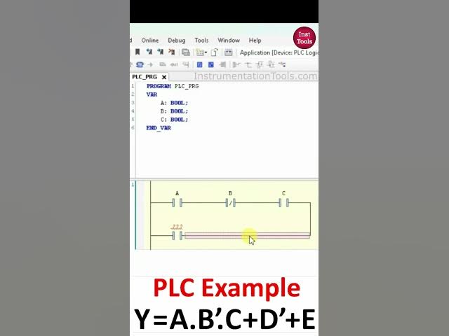
a ladder diagram for a boolean
0:05
expression. Y is equal to a dot b dot c
0:10
plus d + e. So we have one output that
0:15
is y and we have five inputs a b c d and
0:19
e. So firstly I will open cordises.
0:25
After that double click on the PLC
0:29
So here we will be drawing ladder
0:31
diagram. So firstly we have to uh draw
0:35
ladder diagram for a dot b dot dot c.
0:39
That means we have to connect these
0:41
three inputs in series. So firstly I
0:44
will insert a contact here and this will
0:50
then we have dot. Dot means in series.
0:54
Okay. So uh then we have B not B not
0:57
means there is a negated contact and
1:00
normally closed contact. So we'll insert
1:02
a negated contact and this will be B.
1:05
And after that we have a dot C. The dot
1:09
means in series here. So we will use a
1:12
cut a normally open contact and this
1:15
will be C. Now we have to connect uh
1:18
these contacts in parallel. So we will
1:21
uh uh select these inputs.
1:25
Okay. Uh uh I just press the shift
1:28
button and select all of these and then
1:31
insert contact parallel just like this.
1:35
And we will delay this. Okay. So we have
1:39
a dot b dot dot c then we have plus that
1:43
means we have to connect in parallel
1:45
then we have d not. Okay. So this will
1:48
be a normally closed contact. So we will
1:50
delete this normally open contact. So
1:53
this will be d. Okay. So as of now uh
1:57
it's a dot b dot c plus d. Then we have
2:03
one more plus that means we have to
2:06
connect in parallel. Okay. So we will
2:09
insert a contact para. Okay. So we have
2:12
plus then e. So for e we will be using a
2:16
normally open contact. So this will be a
2:20
and after that we will insert a coil. So
2:23
we'll insert a coil and this coil will
2:26
be Y. So output Y will turn on when A is
2:31
on, B is off and C is on. The output Y
2:34
will turn on. So instead of A, B and C,
2:38
Y will turn on when D is off. If D is
2:42
on, the output Y will not turn off. And
2:46
we can also control this output Y with
2:49
the input E only. So when input E is
2:53
turned on, the output Y will turn on.