
Arduino Opta: Step-by-Step Guide to Wiring a 24V Discrete Input Sensor
Jun 1, 2023
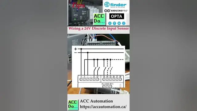
We will be wiring an Opta PLC input to a 12 to 24 VDC sensor. The Opta IoT PLC datasheet specifies that the supply voltage should be 12 to 24VDC. The inputs will turn on when the voltage reaches 6.6 VDC and off when it drops to 4.46 VDC.
The Opta's discrete inputs (on/off) will switch to +DC voltage. Since the controller input common is at 0 VDC, this is considered a sinking input. You can refer to a post that covers the wiring of NPN and PNP 3-wire sensors for more information.
We wired a 10 to 36 VDC CK1-00-2H capacitive proximity sensor as a PNP output. Our Opta PLC input will replace the load shown as a box in the sensor wiring diagram.
Wiring of NPN and PNP 3-Wire Sensors
https://www.automationdirect.com/adc/shopping/catalog/sensors_-z-_encoders/capacitive_proximity_sensors/18mm_round/ck1-00-2h
Download the software from the following URL link.
https://www.arduino.cc/en/software
Arduino Opta IoT PLC Series
https://accautomation.ca/series/arduino-opta-plc/
Arduino Opta PLC - IoT and Industry 4.0 Enabler
Finder OPTA 8A Series - Tutorials
https://opta.findernet.com/en/
Datasheet
https://cdn.findernet.com/app/uploads/S8AEN.pdf
Quickstart Sheet
https://cdn.findernet.com/app/uploads/IB8A04EN.pdf
Show More Show Less #Industrial Materials & Equipment