0:00
Welcome to Mbots. I'm Dustin and this is
0:03
the LED blinker circuit.
0:17
Welcome to this video on the LED blinker
0:20
circuit. This circuit is part of our
0:23
circuit component super series on the
0:26
website. This video is to show the
0:29
assembly of that LED blinker circuit.
0:33
I'm not going to go too much into how
0:36
this circuit works. Some of that was
0:39
gone over on the website on that third
0:44
part of this 12-part series titled How
0:48
Components Work Together in Real
0:50
Circuits: Having Components Join Forces.
0:53
I'll leave the link to everything I'm
0:56
talking about here down in the
0:58
description of this video and I might
1:00
also uh place some imagery in the video
1:04
as well. So again, all I wanted to do
1:07
for this video was to just show the
1:10
assembly of the LED blinker circuit and
1:13
let's jump into that right now. So, as
1:15
you can see here, I have in front of me
1:16
the components and items that we'll need
1:19
to assemble this LED blinker circuit. I
1:23
have here a basic 9V battery with a
1:28
battery snap connector attached to it
1:30
ready to go with its uh negative and
1:33
positive uh lead wires. I have a
1:38
breadboard here. I have two 10
1:41
microfarad polarized capacitors or
1:44
electrolytic capacitors. I have a couple
1:47
of jumper wires here, one red one and
1:49
one orange one. I have another couple of
1:54
longer red jumper wires here. These are
1:58
more of your typical solid core uh
2:02
jumper wires. I'll have to bend these
2:04
later to get them to uh bend the way I
2:08
need them to or bend them in submission.
2:10
I have another couple of smaller blue
2:13
jumper wires here. Also, the typical
2:16
solid core wire. I also have a couple of
2:19
resistors here. These are two 47,000
2:24
ohm resistors or 47 kohm resistors. And
2:27
I have two other uh resistors here that
2:30
are both the value of 470 ohms. Right
2:36
uh NPN transistors. These happen to be
2:42
transistors. And I have my red and blue
2:46
LEDs here. And these are the LEDs that
2:50
we're going to try to get to uh blink
2:53
for us for this LED blinker circuit. So,
2:56
if you were to look at the blog post for
3:00
this particular circuit in our circuit
3:02
component super series, that's the post
3:05
how components work together in real
3:07
circuits or part three of the series. It
3:10
starts off with connecting the 9volt
3:12
battery to the breadboard, but I'm not
3:14
going to do that. I'm going to go ahead
3:15
and put the components onto the board
3:18
itself. And then the last thing I'll do
3:21
is connect the 9volt battery to the
3:24
breadboard. So, the first thing that I'm
3:26
going to do is go ahead and put the two
3:33
the two NPN transistors onto the
3:37
breadboard. And I have the transistor
3:42
face or the flat face of the transistor
3:47
pointing directly towards me. And the
3:50
legs of this particular NPN transistor
3:55
going from left to right is emitter,
4:00
base and collector. So the emitter is on
4:04
the left, the base is in the middle and
4:07
the collector is the right lead with the
4:10
flat face facing towards me. So again,
4:14
I'm going to place both of these
4:15
transistors flat face facing towards me.
4:18
And I'm going to put the three legs of
4:24
on column B or excuse me, column C in
4:29
the rows four, five, and six. So I have
4:34
the emitter in column C, row four. I
4:40
have the base lead at column C row five
4:45
and I have the collector lead on column
4:54
And if I pick up my circuit here
4:59
and show you a little closer,
5:01
that's the flat face of this transistor.
5:04
You can see it's a PN222A.
5:08
I have its emitter leg on column C, row
5:12
four, the base at column C, row five,
5:16
and the collector at column C, row six.
5:23
So next, I'll put the second transistor
5:26
again having the flat face facing
5:29
towards me. And I'm going to place the
5:31
legs for this transistor on column C and
5:35
at rows 14, 15, and 16. Next, what I
5:39
want to do is I want to connect the
5:43
emitters for both of the transistors to
5:47
ground. And I'm going to have this rail
5:52
here, this blue rail with the negative
5:55
sign be my negative or common ground
5:59
rail. And I'm going to have this red
6:03
power rail here with the plus sign be my
6:07
positive power supply or the positive
6:11
side of my power supply for this rail
6:13
here. So, I'm going to reserve those two
6:16
as my positive and negative rails. So,
6:18
I'm going to take one of my shorter blue
6:21
jumper wires and place one jumper wire
6:25
at column B into row four that's in line
6:37
this transistor's emitter leg going to
6:41
ground. So, just so you know, looking at
6:44
the schematic that is provided on the
6:46
website, this is my Q1 and Q2
6:53
And I'll take this other blue jumper
6:58
wire. And just as I did for the first
7:02
transistor, I'm going to place one side
7:04
of the jumper wire in line with the
7:08
emitter pin of or the emitter lead of
7:12
the second transistor and the other end
7:14
of that jumper wire to ground. So now I
7:17
have both of the emitters for each of
7:19
these transistors going directly to
7:22
ground. Next, I'm going to take one of
7:24
my 10 microfarad capacitors.
7:28
Making sure that I have it in proper
7:34
This gray line here is
7:39
referencing the negative lead of this
7:43
capacitor, this polarized capacitor.
7:46
That would be the cathode. So that gray
7:50
line here means that this lead here is
7:54
the negative and the other one is the
7:57
positive. Okay. So I'm going to place it
8:01
in row H. Sorry, I'm going to place it
8:06
in column H at rows five and six. And
8:09
I'm going to take the second 10
8:13
microfarad capacitor and I'm going to
8:16
place its leads into column H rows 15
8:22
and 16. So just so you know, I have the
8:26
cathode of this capacitor representing
8:30
C1 from the schematic. It's negative
8:34
lead going in to column H, row six. and
8:41
C2 here as referenced from the schematic
8:44
from the website. I'll also provide that
8:46
schematic down in the description below.
8:49
This capacitor C2, its negative lead is
8:58
And I'll give a closeup view of what
9:02
that looks like so far.
9:05
So, this is how the circuit setup is as
9:15
we'll continue on from there. Next, what
9:17
I'm going to do is I'm going to go ahead
9:21
the red LED onto the breadboard.
9:24
And I'm going to take the longer lead of
9:29
the LED. This longer lead here is going
9:32
to be the anode or the positive lead of
9:38
this LED. And I'm going to place it near
9:42
the first capacitor, capacitor C1, as
9:46
referenced from the schematic. And I'm
9:47
going to place that anode into column G
9:51
row 4. And then I'm going to place the
9:53
cathode of the LED on column G row 5.
9:57
And that cathode of the red LED will be
10:03
that positive lead of the capacitor. And
10:07
now I'm going to take one of the 470 ohm
10:13
and I'm going to place one of its leads
10:16
in line with the anode of the red LED
10:20
and the other end of the resistor
10:23
into my positive power rail here. And
10:27
now I'm going to take the blue LED and
10:29
I'm going to do the same thing as I did
10:31
with the red LED. I'm going to place its
10:34
longer lead or the positive lead of the
10:39
blue LED into column G row 14. And the
10:44
negative lead or cathode of the blue LED
10:46
is going to be at the point column G row
10:50
15 which is in line with the positive
10:54
leg or lead of this second capacitor or
10:57
C2 if you're referencing the schematic.
11:00
Again, I'm going to take one of these
11:02
470 ohm resistors. I'm going to place
11:04
one end of it in line with the anode of
11:08
the blue LED and the other end of the
11:11
resistor. Its leg is going to go into
11:14
the positive power rail of the
11:17
breadboard. So now in order to complete
11:20
the timing side of the circuit, I have
11:24
my timing capacitors. Now I'm going to
11:26
take my timing resistors, which is just
11:29
a couple of 47 km resistors or 47,000
11:35
ohm resistors. I'm going to take one of
11:37
those 47 K ohm resistors and I'm going
11:40
to take one lead or one end of that
11:43
resistor and place it in line with the
11:46
negative or cathode lead of capacitor C1
11:53
as referenced on the schematic. So, I
11:56
have one lead of that 47 km resistor on
12:02
column I, row six. And I'm going to take
12:06
this other 47 km resistor, and place one
12:10
end of it in line with this second
12:14
capacitor, its cathode lead or negative
12:21
row 16. And the other end of that
12:24
resistor is going to go into the
12:26
positive rail for our power supply. So
12:32
and show you a little closer,
12:36
this is how the circuit looks so far
12:41
and where everything is going.
12:46
So you can get a good look at it.
12:50
So now I'm going to continue and we're
12:52
almost done here. I'm just going to
12:56
first connect the negative of each the
13:01
negative lead of each capacitor to the
13:04
base of its opposing transistor.
13:07
I'm going to do that first because it's
13:09
just going to be easier that way for me.
13:11
So, what I mean is I'm going to if I'm
13:14
looking at the first capacitor or
13:16
capacitor C1, if you're looking or
13:20
referencing the schematic,
13:23
I'm going to put one end of my jumper
13:25
wire in line with the negative terminal
13:29
of that capacitor and I'm going to place
13:31
the other end of this jumper wire at the
13:33
base of this opposite side transistor.
13:38
So, if you're referencing the provided
13:42
I'm going from the negative leg or lead
13:47
or the cathode lead of capacitor C1
13:52
to the base of transistor Q2 as
13:58
referenced in the provided schematic for
14:01
the LED blinker circuit. I'm going to
14:06
red jumper wire here and I'm going to do
14:10
two or C2 as referenced on the schematic
14:14
the same as I did for capacitor C1. I'm
14:17
going to take this jumper wire and place
14:20
it in line with that capacitor C2 as
14:24
referenced in the schematic. I'm going
14:26
to place it in line with its cathode
14:29
lead. I'm going to take the other end of
14:31
this jumper wire and place it in line
14:42
transistor Q1, as referenced on the
14:45
provided schematic for this LED blinker
14:48
circuit. So, if I show you a closeup
14:56
that I've taken one of these long red
15:00
jumper wires. They're kind of too long,
15:03
but that's what I have. I place one end
15:05
of that jumper wire in line with the
15:08
cathode of this capacitor. This is
15:10
capacitor C1 as referenced on the
15:12
provided schematic. That is at column F,
15:16
row six here. The other end of this same
15:21
jumper wire goes in line with the base
15:26
of this transistor, transistor Q2 as
15:29
referenced on the schematic diagram at
15:35
And this other second jumper wire, one
15:38
end is placed at column F, row 16 in
15:41
line with the cathode of capacitor C2
15:45
here. And the other end is placed at the
15:48
point column D, row 5 in line with the
15:52
base of transistor Q1 as referenced from
15:56
the schematic diagram provided.
16:03
Now I just need to make the connections
16:05
from the collectors to the capacitors.
16:09
Therefore closing the path that we need
16:12
for our timing part of the circuit. I'm
16:17
going to take one end of this orange
16:18
jumper wire and place it in line with
16:21
the positive lead of this capacitor C1.
16:25
I have it at the point column J row
16:29
five. And I'm going to take the other
16:31
end of it and place it in line with the
16:40
that is at point column E, row six on my
16:44
breadboard. And I'm going to take this
16:47
blue jumper wire here. And similarly,
16:50
I'm going to place one end of this
16:52
jumper wire in line with the anode of
16:55
capacitor C2 here. It's this capacitor
16:58
here with its positive lead or its
17:02
anode. And I'm going to place the other
17:03
end of this jumper wire in line with the
17:06
collector of transistor Q2 as referenced
17:11
on the schematic. And I've placed it at
17:14
the point column E row 16 on my
17:18
breadboard here. So, before I hook up
17:21
the battery to my circuit and test this
17:24
out, I'm just going to show you a closer
17:26
look here as to how this circuit looks.
17:30
It looks awful right now, but I'm using
17:34
what I have to be able to accomplish
17:36
what it is that we want to do, and
17:38
that's to create this simple LED blinker
17:50
So the next thing that we need to do is
17:53
just hook up the power
17:57
our circuit here. So to do that, I'm
18:00
going to take the positive
18:03
lead of my 9volt battery and place it
18:08
into my positive power rail here. And
18:10
then I'm going to place the negative
18:14
lead of my 9volt battery somewhere, it
18:18
doesn't matter, on my negative rail. And
18:23
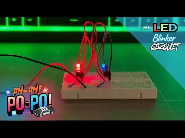
the circuit lights up. And we have a LED
18:29
So, if you're curious about creating
18:31
this circuit yourself and need more on
18:36
content and how the circuit works, I
18:39
encourage you to check out on how
18:41
components work together in real
18:43
circuits where you can find more about
18:46
this particular LED blinker circuit and
18:48
more on components. So, I highly suggest
18:51
that you go check out that circuit
18:52
component super series where you can
18:54
learn more about circuits and
18:56
components. It's a 12-part super series.
18:59
This is for part three of that series
19:02
and we'll eventually work our way to
19:05
creating a robot and doing much more in
19:07
that series. So, I highly suggest you go
19:09
check that out. I appreciate you
19:12
spending your time with me here. I hope
19:14
that you were able to create this
19:15
circuit. It's a lot of fun and it's
19:17
really neat. And if you ask me, I think
19:19
it looks like police car lights. So,
19:22
this was a really neat and fun circuit.
19:24
I hope you try it. Again, thanks for
19:27
joining us here at Mbots. Until next
19:30
time, keep at it and stay motivated.