live_tv
Livestream Starting Soon
00
Hours
:
00
Minutes
:
00
Seconds
Up next in 10

SolidWorks Modeling & Drafting 07 | SolidWorks Tutorial | SolidWorks Part Modeling |
Jan 6, 2025
#SolidWorks #solidworksmodeling #solidworkstutorial
In this video I have explained How to Model Part in SolidWorks.
▶️ Download This Tutorial Source File From my Ko-Fi Store-:
https://ko-fi.com/s/d8a110f255
▶️ Visit my website for more info-:
https://mechnexus.com/
▶️ The Complete SolidWorks Course : From Zero to Expert!-:
https://www.udemy.com/course/solidworks-complete-course-zero-to-expert/?referralCode=B30458218EA1375DDB6E
▶️ Buy Me a Coffee
I am very grateful that you watch my videos and I am constantly trying to improve the quality of the videos on this channel. If you'd like to help me do this, please consider supporting me so that I can to continue to produce content for your enjoyment.
👉 Help support this channel by buying me a coffee: https://ko-fi.com/mechnexus
👉 Indian User can Support My Work Using my UPI ID: amar.patel456@ybl & amar.patel456@axl
All donations will be used to purchase equipment to improve my productivity and increase the quality of the content that I produce. Your kind support will help to grow this channel. Even if it's just enough to buy me a coffee every little helps and this will be repaid in full through my sharing of knowledge.
Show More Show Less View Video Transcript
0:00
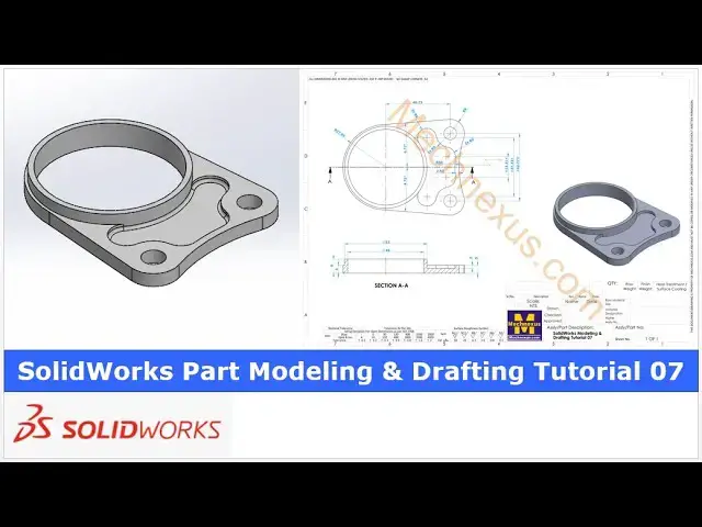
Hello friends welcome to Solid Works tutorial and in this tutorial we will model this part and you can see that uh
0:07
I have already model it with respect to the orthographic View and you can see
0:12
that uh our uh model is matching with the isometric view of the our
0:18
drawing we will not only create the model but we will also create a 2d
0:23
drawing as you can see that uh I have already created it and I will uh show
0:29
you from the scratch how you can model this part and as well as create the
0:34
drawing so I will close this file and create a new
0:40
file you can also visit my website macn nexus.com and you can visit this solid
0:47
works tutorials tab where I have written so many tutorials on solid works where
0:54
you can follow the stepbystep guide to model the parts
1:00
if you like my method of teaching then you can also support me on kofi.com you
1:06
can buy me a cup of coffee your small support will help these channels to grow
1:12
and it will motivate me to create more awesome content on solid works so let's
1:18
come back to our tutorial so here I have created a new file and uh first thing which we will do
1:26
is to create this uh base feature on the top plane so I will uh select the top
1:32
plane and uh create a sketch so first thing which I will do is to create a
1:38
construction Circle so here I have a created a circle
1:44
and uh now I will uh give the diameter of uh
1:50
92 and I will uh make it as a
1:56
construction and now I will uh draw a horizontal construction
2:02
line select a line tool and create a line and now I will select it and uh
2:10
made it for the construction and now here is
2:19
a radius is of 27.5 so let's uh create a three-point
2:27
Arc and I will look create a three-point
2:37
AR and uh make this and this as a vertical
2:44
relation this and this as a vertical
2:50
relation and Define
2:57
this 54.1
3:07
or we can uh create a circle which we will make at a construction and we will
3:14
delete this Dimension Let's uh make it a
3:21
construction and uh select smart Dimension and this is of a diameter 54.1
3:32
and here I will delete my existing sketch and
3:39
now I will select a three-point Arc select this and this and I will make
3:46
it equal and now I will move this
3:56
Dimension and now let's switch to the our uh trying view so here from Center
4:01
to this is of a 4.73 so what I will do I will uh create
4:09
a
4:15
circle and this is the R9 so I will select a smart
4:21
Dimension select a smart Dimension and give it 18 mm
4:31
and now give its position it is a 4.73 so let's select this and
4:42
this and now this is the 42.7 7 and it is a
4:50
symmetric so I will select this and
4:56
this and uh 40 77 IDE by
5:04
2 so now you can see that it is a perfectly coming here so here what I will
5:16
do I will uh make this two Dimension as a
5:23
driven let's select this and uh this as well and make it uh
5:31
driven and let's select this point and this and uh add a coincidence
5:41
relation now I will make it a undriven similarly
5:48
this I will make a undriven so now here is a coincidence so
5:55
one of the dimension let's make it driven so that it it will be fully
6:01
constrained and now here I will make this uh Circle as a
6:08
constraint now select the line create a line
6:15
tool select this and this and uh add a
6:21
tangency say okay and now here is a three-point Arc
6:30
but we will create one more circle on the other side as a construction Circle so create a
6:38
circle and make this and this add a vertical
6:45
relation make this and this circle as a coincidence
6:51
relation and select this and this and uh
6:56
made it equal and also make it a
7:04
construction and now let's use the trim tool to trim the extra geometry and now
7:11
we will create a three-point Arc which is of a radius
7:16
r60 so I will select a three-point
7:28
Arc now I will select this uh diameter and this
7:39
Arc and add a tangency similarly on other side select
7:44
this uh Circle and R and uh add a tangency say
7:51
okay and now let's uh give the radius
7:59
which is off 60 and
8:05
now we will uh create the same line on the other side so let's select a line
8:15
tool create a line select this and
8:20
this and uh add a tangency say okay and
8:26
now select triam tool and trim it now here we will create a three-point AR and
8:34
uh we will close our
8:41
profile select
8:47
this there was the another option as well you can trim this geometry and
8:53
remove this construction but I prefer the construction geometry a lot
9:00
while the sketching because the construction geometry provides the reference
9:05
idea let's uh close it and let's create the first pad of 5mm this 5mm Dimension
9:13
we can see here so select the sketch click on
9:19
exclude and uh provide the pad dimension of a fmm say
9:27
okay and now we will uh create the cut
9:33
of a diameter 48 so select the top face and uh click
9:41
on the sketch now select the top
9:48
view select a
9:53
circle select smart dimension
10:04
48 come out of the sketch select the sketch click on uh
10:11
extrude cut and say it through all say
10:19
okay now there is a diameter of uh
10:26
52 which is the pad so so let's uh select this stock face and uh click on
10:34
the sketch and we will select this inner diameter and click on the convert
10:40
entities and uh we will select the top pH and click on the circle create a
10:48
circle and uh provide the diameter of for
10:57
502 and now uh we will create a pad so here is a total of 9 mm total height and
11:06
we have already created this 5mm pad so this is the pad of a
11:14
4mm so select the sketch click on extrude provide the pad of uh 4
11:24
mm and now let's switch to the isometric view
11:31
here we have a created this based profile and we have a created this pad and now we will uh create this cut so I
11:39
will select the top phas and click on the sketch and make this phase
11:47
normal and now first thing which I will do is to
11:53
project this geometry click it and click on convert entities and make this phase normal and
12:02
now select a three-point
12:09
Arc which is of R6 Let's uh again select a threo
12:16
AR and uh select this and this and uh
12:21
add a tangency same thing we will do here select this and this and uh add a
12:30
tangency at the same time I will select both this Arc and I made it
12:37
equal and uh give the center to Center
12:44
dimension which is 37. 334 and uh we will make it
12:52
symmetric from the origin now I will press the equal symbol
13:00
and select this and divide by two say
13:06
okay and now we will create this arc on both the
13:12
side so select
13:19
it this site and this
13:26
side select uh this and this and add a
13:32
tangency say Okay select this and
13:38
this and add a tangency and now this is the
13:46
R6 so I will uh move
13:54
it now I will select a three-point Arc
14:00
create an arc on this side and create an arc on this
14:07
side and now if you see here this R9 is a
14:14
concentric with uh outer fillet so I will select this outer radius click on
14:20
convert entities same on the other side select
14:26
this and click on convert entities select this and this and made it for the
14:35
construction and now select this Center and this
14:42
Center and click on the merch and now this
14:49
Center we will merge with uh this click on
14:55
merch and now let's give the diam menion this is of
15:06
R9 okay and now this is of R
15:17
six and we will select this and this and uh
15:25
made it equal now
15:30
we will add a tangency select this and this and add a
15:36
tangency similarly here select this and this and add a
15:43
tangency now I will uh move this Arc point and now I will
15:50
uh select a three-point Arc select this and this
16:00
and I will select this Arc and this outer one and made it a
16:07
concentric and now let's uh add a tangency select this and this and add a
16:13
tangent select this and this and add a
16:20
tangents now let's uh move
16:26
it press contrl Z so
16:32
here select smart Dimension select this and this which is
16:39
of a
16:49
2.5 here is a 2.5 so our sketch is fully constrained and we will create a cut of
16:56
2 mm the 2 mm depth we can see here
17:03
now I will come out of the sketch select the sketch click on
17:11
extrude and here we will give the depth of uh 2 mm so here you can see that
17:20
uh thin feature we will remove and here is a problem of a open
17:26
loop so we will go to the edit skage and here
17:33
if you see that uh here is a open loop so what I will do
17:39
I will select this projector geometry and made it the
17:45
construction and I will again select a three point Arc select this point and
17:51
this point and I will made it equal select
17:58
this and this and say equal say okay and come out of the
18:04
sketch now it will not show the problem of open loop select the sketch click on
18:11
extrude and give the depth of 2 mm say
18:18
okay now we will uh create these two
18:24
holes which is of uh diameter 8 so I will create in a sketch select the
18:32
face and create a sketch and now I will switch to the normal
18:38
View and here I'm not going to make with a whole wizard because it is a plain
18:43
drill hole so I will snap my point and create a two
18:51
Circle and now I will select this and this and uh made it equal
18:59
and I will constrain uh one of the diameter which is of 8 mm and now I will
19:07
uh close it uh select the sketch click on extrude
19:13
Cut and I will say it through all and say
19:20
okay and now I will provide the fillet of 1 mm to the
19:26
inside which is not given our reference drawing but I will provide here select it go to the
19:36
fillet and here give the 1 mm so you can see that it automatically
19:44
took the tangency propagation and it created the fet all ages say
19:54
Okay so this completes our model and now we will will creates its
20:01
drawing Let's uh set our model to the isometric view now here is my drawing template and
20:10
now I will go to the model view select my model and here I will place my current
20:17
model view and now I will select my first View
20:25
and uh set my scale and I will
20:34
uh enlarge my here I have used my scale odd scale
20:42
because my scale on a template is a
20:49
NTS and now let's uh give the dimensions so our
20:55
first Dimension is r 27 05 so I will go
21:00
to The annotation tab select smart Dimensions select
21:05
it okay and now angle is of uh
21:12
4.72 so let's give the angle so in the my case this uh angle is coming
21:19
different say okay and uh let's give this
21:26
angle later we will ident ify which dimension is not matching select smart
21:33
Dimension select this and uh this so this and this angle
21:40
is a s uh same and now let's check this
21:47
distance so it is a 41.4 so let's uh fix
21:55
this so I will uh go to the
22:00
and here I will go to the my base view here and
22:06
now I will uh select angle tool and give here angle so
22:15
obvious leave this Dimension driving say
22:21
okay and now here is a conflict in the the
22:29
dimensions so I will select it and let's say it
22:37
driven and it is a
22:43
40 73 so let's change it 40.
22:50
73 okay so now you can uh see the
22:56
angle angle is a k 4 . 72 so this is the driven one so we have uh matched it and
23:04
now we will uh close it and now we will go to the drawing
23:12
tab so you can see that uh our angle is
23:18
updated let's move it
23:28
and now here is a radius
23:35
R9 and uh from this Center to this Center is of
23:41
4277 so I will
23:51
uh so this is a
23:57
42.760890 symmetric so I will go here and uh provide the equal
24:04
symbol and I will uh move this uh Center Line and now I will select it and add a
24:14
center Mark I will select this radius and add a center Mark say
24:20
okay and uh now select smart dimension
24:30
it is a
24:58
here I will select this options and uh I will move this 60 mm
25:06
Dimension to the inside
25:11
here and I will move this two Dimension
25:19
outside and let's uh adjust the dimension
25:35
now round of the 60 Dimension set it none and here is of
25:42
2.5 instead of that we can also give the radius but we
25:48
will give it a 2.5 as per reference say okay and this is of radius
25:56
R six select smart Dimension select this
26:02
radius and this is as a two locations so round off it and from here provide the
26:12
2X and uh this radius is of R9 so I will select this and
26:19
R9 same way I will uh round off it and give the 2X
26:29
and this is the R9 at two locations so I will select this radius and make it none
26:37
and uh give the
26:43
2x I will uh select
26:50
it let's uh move it
26:58
and move this uh 2 into R six yeah and now here I will uh select
27:07
the diameter give the
27:13
diameter and this is as a two locations so give it a
27:20
2X and set it none and let's
27:26
see what is the remaining in this view so here is a dimension of
27:34
R6 so I will uh give it on uh this
27:46
side say it none and uh give it a
27:57
2X so here the minor difference which we are getting because this uh dimension of
28:04
R six this is not exactly R six it is a something like the
28:09
5.97 98 so this is the driven
28:15
Dimension now we will uh create a section View
28:32
to create a section view we will uh select our view go to the drawing tab click on the
28:38
sections select this and uh made it coincidence and say
28:47
okay and uh place our section View and
28:53
now we will uh change the font size of a label of our
28:58
sections I will set it to the 16 and set it to the
29:04
bolt and I will also label section B to a because uh it is a
29:11
first
29:17
section now let's uh give the dimensions go to di anotation step
29:22
select smart Dimension and uh this is of a 5mm
29:29
I set it none and this is the depth of a cut is of a 2 mm so give it a 2
29:38
mm and set it
29:45
none and here is of radius
29:52
R1 and now I will uh insert the center line and show this D diameter
29:59
42 uh 52 and 48 select uh this two
30:07
edges and go here on Center Line click on select view say
30:13
Okay select smart
30:18
Dimension select this and uh this give
30:23
it a 48 and uh select this
30:28
and this give it a 52 and this is of 5 mm for as a
30:37
reference and total height is of 9
30:43
mm and now here I will press the control
30:55
key select this this
31:01
this and this and uh I will make it a round
31:06
off and let's uh move this
31:11
Dimension now we will adjust the view uh we will
31:17
move our base view to the top so you can see that
31:23
uh we have successfully converted this orthograph graphic
31:28
drawing in a solid works drawing and now here uh we will Define this one
31:37
dimension for this Center so select it and uh click on add a center Mark select
31:44
this and uh add the center marks and now select the dimensions tools from Center
31:52
to Center and it is a 13.2
31:59
Let's uh make it Precision One Z and add the equal
32:05
symbol which means that it is a symmetric and
32:12
now let's uh move it
32:32
now we will uh place this isometric view so we will go to the drawing tab
32:38
click on the model click on our model and select here isometric
32:45
View and now select our uh View and
32:51
uh give here shade it and let's change the
32:56
scale uh Let's uh make it uh larger so let's make it to the
33:10
6 and let's uh move our
33:16
Pew and let's move our base view to the little bit left hand
33:22
side and adjust our isometric view say okay
33:28
now we will insert the title here so I will go to the annotations tab
33:35
click on the note and here the title of uh this drawing is a
33:43
solid works modeling and drafting 07
33:58
and I will press CR a and make this bold
34:05
sayc so you can see that uh we have not only created the 3D model but uh we have
34:12
also created the manufacturing drawing so this is all about this
34:18
tutorial on how to model A Part and create a drawing in a solid works thank
34:24
you for watching and thank you for your valuable time e