live_tv
Livestream Starting Soon
00
Hours
:
00
Minutes
:
00
Seconds
Up next in 10

FreeCAD Part Modeling Tutorial 134 | FreeCAD Tutorial | 3D Modeling Tutorial | FreeCAD Community |
Apr 24, 2025
#freecad #freecadtutorial #FreeCADforbeginners
In this video I have explained How to Model Part in FreeCAD with the help of part design Workbench.
▶️ Join my channel membership and keep supporting my work:
https://www.youtube.com/channel/UCcn6z2whMaFu-_LDsEXCfVA/join
▶️ Visit my website for more info on FreeCAD-:
https://mechnexus.com/
▶️ Get my FreeCAD Crash Course for beginner-:
https://www.udemy.com/course/freecad-course-for-beginner/?referralCode=3BA9B526A12F96295D44
▶️ Download Source File of Tutorial-:
https://mechnexus.com/mechnexus-youtube-tutorial-source-file/
▶️ Buy Me a Coffee
I am very grateful that you watch my videos and I am constantly trying to improve the quality of the videos on this channel. If you'd like to help me do this, please consider supporting me so that I can to continue to produce content for your enjoyment.
👉 Help support this channel by buying me a coffee: https://ko-fi.com/mechnexus
Show More Show Less View Video Transcript
0:00
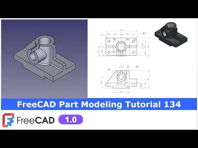
hello friends welcome to free tutorial
0:03
and in this tutorial we will model this
0:05
part as you can see that I have already
0:08
model it and is it is matching with the
0:12
reference drawing isometric
0:14
view we will refer the front and top
0:17
view and we will create this part from
0:20
the scratch so I will close this file
0:23
and create a new file and uh for this
0:26
tutorial I am using the frecad version
0:29
1.0 so you must have at least fread
0:33
version 1.0 or higher
0:38
you can also visit my website
0:41
macexus.com where I write articles and
0:44
tutorials on a free CAD and you can also
0:48
access my 3D part library of a free CAD
0:53
you can download the part from here and
0:56
you can use in your projects with
0:59
modifications
1:01
you can also access my 2D drawing
1:04
library where you can u download this 2D
1:09
drawings and uh you can create 3D models
1:13
with respect to these
1:16
drawings you can also support me on
1:21
coffi.com you can buy me a cup of coffee
1:25
your small support will uh help this
1:27
channels to grow and it will motivate me
1:30
to create more awesome content on uh
1:34
free CAD you can find my Kofi donation
1:37
page link in a video description as well
1:40
as you can also see my Kofi page URL on
1:44
this
1:46
header so let's come back to our
1:50
tutorial here I have created a new file
1:53
and now I will insert my body and I will
1:56
on the origin plane and now I will
2:00
create my first sketch so we will first
2:05
create our first sketch on a front plane
2:08
which is exit
2:10
plane and uh click on the
2:14
sketch and let's uh hide the origin and
2:18
now we will first create this
2:22
profile so first we will uh select a
2:26
rectangle tool and create a
2:29
rectangle and now I will make this
2:33
rectangle
2:34
symmetric select uh this point this
2:38
point and the
2:40
axis and now we will uh give the
2:43
dimension so this is the
2:50
150 and now height is of
2:57
25 which we can see here and now our
3:02
sketch is fully constrained we will
3:05
extrude it to the distance of 85 which
3:08
we can see in top view
3:12
press zero and uh select the sketch
3:15
click on the pad and give the 85 and
3:21
uh make it symmetric to the plane and
3:25
say okay and
3:28
now we will uh create this round profile
3:34
select the face and click on the sketch
3:36
and uh we will create a
3:39
circle and uh this is of a diameter if
3:43
you
3:44
see so this is a diameter 52
3:48
here so we will uh give it 52 click on
3:54
close and uh
3:56
now create a pad of a 60 mm select it
4:00
and create a pad and give it a 60 say
4:04
okay and now we will uh create this rip
4:11
here so we will select the face and
4:14
click on the sketch press zero for right
4:17
orientation select the top and now we
4:21
will project this outer
4:24
diameter and we will also project this H
4:29
and now I will uh create a
4:33
rectangle and now I will uh delete this
4:37
line and I will click on the trim tool
4:41
and uh trim this extra
4:44
geometry and now here I will select this
4:48
point and line and add a coincidence and
4:52
now I will make this symmetric select
4:55
the symmetricity select this point this
4:57
point and the
4:59
axis and this is of a 10 mm thick which
5:02
we can see here select smart
5:05
dimension and give the 10 mm and now to
5:09
close our profile we will create a
5:11
threepoint arc and which we will make
5:14
equal to our projected diameter so go
5:18
here and select a threepoint
5:22
arc and uh select this and this and uh
5:27
made it equal so our profile is fully
5:31
constrained now select the sketch click
5:33
on the pad and from here select up to
5:37
face and uh define this face
5:43
now let's uh create the next feature
5:46
which is the rib on the other sides so
5:49
we will do the same procedure select the
5:52
top face and click on the
5:55
sketch and now let's switch to the
5:57
isometric and switch to the right
6:00
orientation and now here we will again
6:03
project this
6:08
diameter and uh also project this age
6:12
now click on the rectangle and create a
6:16
rectangle and
6:18
now let's select this line and delete it
6:22
and now in the same way we will uh trim
6:25
this extra
6:27
geometry and now I will select a
6:31
threepoint arc and create one
6:34
arc and I will select this arc and this
6:37
arc and made it equal now we will make
6:41
it
6:42
symmetric we can also make this
6:49
horizontal if not symmetric we can add
6:51
the relation with this
6:54
age so this is the fully constrained now
6:58
we will close
6:59
it we will uh select the sketch click on
7:02
the pad and from here we will select up
7:05
to phase and select this phase and click
7:07
on okay
7:10
now here we will
7:12
uh create a chamfer so we will select
7:16
the age and click on the chamfer instead
7:19
of equal we will select the two
7:23
distance and we will provide the 60 and
7:27
uh second one is
7:31
49.5 and say okay so you can see that uh
7:36
chamfer is
7:37
created
7:40
now we will uh remove the material here
7:44
which we can see in isometric view
7:48
so we will select the face and
7:51
uh create a sketch and now here we will
7:54
project this vertical and horizontal
7:57
edges so click on the project geometry
8:00
and select these two and now make this
8:05
front and uh create a
8:09
rectangle and now from the bottom give
8:14
it
8:15
45 select
8:17
uh this and
8:20
this give it a 45
8:24
and uh from this
8:28
point it is of 12
8:37
mm now we will create a
8:40
cut select the sketch click on the
8:44
cut set it through all say
8:50
okay and now we will create this pad and
8:55
for this pad we require a datim plane at
8:58
a distance of
9:01
45 which we can see here from this axis
9:04
or we can say the plane we have to
9:07
create a datim plane at a distance of 45
9:10
and then we will create a extrude and
9:13
define the end condition to this face so
9:16
we will on our origin plane and uh we
9:20
will select this exact plane and uh
9:23
create on the DATM and uh now we will
9:26
define the value which is of 45 and say
9:30
okay now we will create our sketch on
9:33
this DATM plane so let's uh hide the
9:36
origin plane and here we will rebuild
9:38
our DATM plane and now we will select
9:42
the DATM plane and click on the sketch
9:45
and now here on this axis we will uh
9:48
create a
9:51
circle and now if you see here from the
9:54
bottom it is of a
9:56
55 so this is the bottom point and this
9:59
is a center and we will define the
10:01
dimension 55 and here diameter is of a
10:06
44 so constrain it with a 44 and uh our
10:11
sketch is fully constrained we will
10:12
press the space bar and hide this datm
10:15
and select the sketch click on the pad
10:18
so here you will not see anything
10:21
because we have to reverse the
10:24
direction
10:26
and we have to define the face then only
10:29
we will see our
10:32
extrusion so say okay and now we will uh
10:37
create our next features so if you see
10:40
the isometric view there are the two
10:42
cuts whose detail we can see here so it
10:46
is a 80 and symmetric on the both the
10:50
side so we will select the phase and
10:53
click on the sketch and here I will
10:55
project this uh vertical and horizontal
10:59
edge click on the project geometry
11:01
select this and this and this one and uh
11:06
select a rectangle tool and uh create a
11:10
two rectangle on the both the side and
11:13
now this is of 80 mm so we will make
11:16
this symmetric click on the symmetricity
11:20
select this point this point and this
11:23
y-axis so now it is symmetric now I will
11:27
define the horizontal distance between
11:29
these two points
11:31
which is of 80
11:34
mm and now this is of 9
11:38
mm so let's uh give it a 9 mm and here
11:43
instead of defining the height here I
11:45
will select these two points and uh add
11:49
a horizontal constraint
11:51
so our uh sketch is fully constrained
11:55
now we will create a cut just select the
11:58
sketch click on the pocket and uh say it
12:02
through all and say
12:05
okay
12:07
now if you see our uh model here in a
12:12
hidden view there is a groove which is a
12:15
revolve cut so we will
12:18
uh on the origin plane and we will
12:21
select the exit plane and click on the
12:23
sketch
12:25
now here I will uh switch to the
12:30
wireframe and hide this origin plane and
12:34
now I will
12:38
uh project the geometry i will project
12:41
this uh age and
12:46
now I will uh select a line
12:51
tool and here I will select this
12:56
point and
12:59
line and add a
13:02
coincidence and now let's uh select a
13:05
line
13:07
tool create a horizontal
13:10
line and then vertical
13:14
line and again create a horizontal
13:19
line and a vertical line and join these
13:24
two
13:25
points and now let's constrain
13:28
it select a smart dimension select this
13:32
axis and this point and this is of a
13:36
22.5 and uh this height is of a 15 mm
13:41
which we can see here and now this
13:45
diameter from this point to this point
13:48
is of uh
13:50
17.5 so now we rotate our sketch and
13:54
everything is a constraint fully and now
13:58
we will remove the material
14:01
inside close it and here we will click
14:05
on this group feature and here fread
14:10
automatically took the
14:15
access so we will say it okay and
14:20
now if you see the isometric view there
14:23
is a cut so we will select the face and
14:27
click on the
14:28
sketch and
14:30
now this uh profile detail we can get
14:33
here
14:35
so first thing which we will do is to
14:38
project the outer diameter so that we
14:43
get a center points to create this
14:46
circle of a diameter
14:48
24 so here I will create a
14:51
circle and uh I will define this 24 mm
14:57
which we can see here now we will uh
15:00
create a rectangle we will uh
15:05
create with a two point and we will
15:08
delete this one and here I will project
15:12
this
15:17
age and select this point and line and
15:21
add a
15:23
coincidence and we will use the trim
15:25
tool to trim the unnecessary geometry
15:29
and uh we will also remove this arc
15:32
and now we will make it
15:35
symmetric so click on the symmetricity
15:37
select this point this point and this
15:40
axis and select smart dimension and
15:44
provide the value
15:46
10 our uh sketch is fully constrained so
15:50
here we wanted to remove the material if
15:53
you wanted to see in a isometric view so
15:56
here we will give the approximate
15:58
distance of 35 so that uh this cut gets
16:02
open in the free
16:04
area so click on close and uh select the
16:08
sketch click on the
16:10
cut and uh give here value
16:16
35 say
16:20
okay
16:22
now here is a fillet of
16:26
R3 it is a common fillet
16:32
so let's give the
16:35
fillet click on the fillet options
16:43
select this
16:45
H this H and this H and provide the
16:50
value of
16:54
R3 because here is a given all
16:57
unspecified fillet R3 say
17:01
okay and now we will uh give more
17:07
fillet on the edges so again select the
17:11
fillet and provide the value 3 mm and uh
17:15
select this edge this edge this
17:19
edge this uh vertical
17:23
edge this horizontal edge same on the
17:26
other
17:27
side select this edge so here is a face
17:32
is selected so we will remove
17:34
it and we will zoom and select the
17:39
sketch if you are facing a problem in a
17:42
selection of age then zoom
17:48
it
17:50
now select this
17:53
edge and this
17:56
age now say
18:00
okay so you can see that fillet is
18:05
created so this completes our
18:08
model so this is how we have
18:10
successfully modeled this
18:13
part let's save our
18:22
part so this tutorial is designed for
18:26
the beginner user of Frecad those who
18:29
want to understand the part design
18:31
workbench in frecad and how we can
18:34
create a solid model in a frecad with
18:37
the help of a part design workbench so
18:40
this is all about this tutorial thank
18:42
you for watching and thank you for your
18:45
valuable time
#CAD & CAM
#Sculpture
#Computer Education